Flow loop testing verifies adaptive model-based choke control system
Model-based control provides consistency, accuracy despite changing system hydraulics, retains robustness in case of gas influx
By Glenn-Ole Kaasa, Vinicius de Oliveira, Jon Åge Stakvik, Kelda Drilling Controls, and Urs Lehner, Reform Energy Services

Managed pressure drilling (MPD) is a technology that enables fast and precise control of the pressure in the well during drilling and completion operations. This is achieved by sealing the annulus and diverting the return flow through a choke manifold. By opening or closing the chokes, one can actively control the backpressure and, indirectly, control the pressure at a desired location in the well.
A main benefit of MPD technology is that it fundamentally improves the possibility to detect and handle well control incidents, such as kicks and losses. The technology provides a closed-circulation system that allows for flow and pressure conditions in the well to be monitored in an accurate manner, thus allowing for influx and loss situations to be detected at an early stage. Once detected, the downhole pressure can be increased or reduced instantly to stop an influx or loss by changing the backpressure provided by the chokes.
To verify and demonstrate how gas influx and two-phase flow can be handled in automated pressure control, an extensive flow loop with unique N2 gas injection capabilities has been set up at AlMansoori’s yard in Abu Dhabi. Figure 1 shows an overview of the test setup.
Automated choke control
In an automated MPD system, the chokes are controlled automatically by a control system. Properly designed, an automated choke control system will significantly improve both accuracy and safety of the MPD operation compared with a manual operation.
A key component is the actual choke control algorithm, which is the part of the control system that ensures robustness and performance of the system. The control algorithm must be carefully designed to be capable of providing consistent pressure control performance for all operational variations.
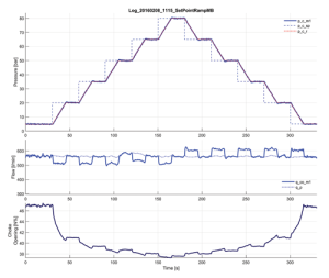
The most common control algorithms used for automated MPD are variants of the conventional proportional and integral (PI) control algorithm, which is broadly used in other process industries. A main limitation of the PI controller, however, is that it does not take into account the strong nonlinear flow characteristics of the choke. This severely limits the ability of the PI controller to compensate for changes in the operating conditions. To be able to handle a wide range of operational scenarios, the feedback gain of the PI controller must be tuned low, which results in slow compensation. A standard PI controller applied for automated choke control in MPD operations will, therefore, exhibit the following inherent performance limitations:
• Different performance at different pressures;
• Slow convergence of transients at low pressures;
• Overshoot during transients when changing pressure set-point at high pressures; and
• High performance only for flows that keep the choke operating in the “sweet spot” of its characteristic.
As a result, a PI controller typically needs frequent attention and retuning to handle different pressure ranges.
Model-based control
Significantly improved performance and robustness is achieved by introducing model-based compensation in the controller. In model-based control, a mathematical model of the well hydraulics is used to anticipate the response and introduce a proactive compensation of operational variations and nonlinearities. By utilizing model-based control, many of the drawbacks of the PI controller can be eliminated.
To achieve high performance over the full operating range of pressures and flow, the controller must be able to change its feedback gain according to the actual operating pressure and choke position. This can be done by incorporating a model of the choke flow characteristics in the controller design. The benefits of such a controller design are demonstrated in Figure 2, where the implemented model-based controller is shown to achieve the following desirable closed-loop properties:
• Uniform (scaled) performance over the full operating range of pressures and flows;
• No overshoot when changing pressure set-point; and
• No need for retuning of parameters depending on pressure operating point.
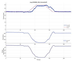
Another drawback with the PI controller is that it provides only reactive compensation in the sense that it relies entirely on feedback from the pressure it controls; it does not take into account any other information, such as pump flow. The PI controller is, therefore, not capable of maintaining a constant downhole pressure in connections without the provision of addition flow to the MPD choke manifold, either from a backpressure pump or by diverting flow from the rig pumps. This is illustrated in Figure 3, where the PI controller, even when tuned for optimal performance at the current operating pressure, is inherently unable to react fast enough to recover pressure during a normal ramp-down of the rig pump with no back flow.
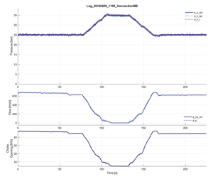
By utilizing feed-forward compensation from the rig pump, the implemented model-based controller is able to maintain a constant downhole pressure, even in the case of fast ramp-down of the rig pump (Figure 4).
Managing well control
During losses, the downhole hydraulics basically remains the same. Losses are, therefore, straightforward to handle by an automated choke control system without modifications. In the case of a gas influx, the situation is more complex. To robustly handle a gas influx incident in automated choke control, the system must be able to cope with large variations in the system hydraulics during the different phases of an influx. The flow loop experiments are set up to enable us to emulate the most important aspects with respect to testing the robustness of the automated choke control system in case of influx. In many ways, this is the ultimate test of the robustness of an automated choke control system.
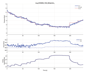
In its initial phase, the gas influx will cause an increase in return flow through the choke. In Figure 5, an influx is induced when the backpressure is reduced from 8.5 to 8.0 bar and increased when the choke pressure is reduced to 7.5 bar. Here, the influx is clearly seen as an increase in the choke flow. In an MPD operation, the corresponding choke flow will occur only seconds after an actual downhole influx, depending on the length of the well and the effective speed of sound of the drilling fluid in the annulus.
As illustrated in the figure, the influx is quickly attenuated by increasing the set-point of the choke pressure to 8.5 bar. In this phase, the main change that could affect the control system is that compressibility increases as gas enters the well. This results in slower transients in the pressure, or lower “system gain,” using control terminology. The increased compressibility slows down convergence of the pressure, but robustness of the control system is fully retained.
The critical phase is when the gas has transported up the well to the choke. When gas enters the choke, it reduces the density of the fluid, which causes an increase in the gain in the choke, i.e., the effect of changing choke opening increases. In the initial phase of circulating out a gas, the high compressibility due to gas in the well will, to a large extent, compensate for the increased gain in the choke. However, in the last part of circulating out an influx, the compressibility will be reduced so that the gas in the choke can destabilize the choke controller, causing severe oscillations in the backpressure.
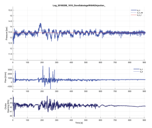
As seen in Figure 6, the Coriolis measurements become erratic when the gas passes through it, which means that measurements of the density and flow rate measurements from the Coriolis become practically useless to the control system. Erratic measurements from the Coriolis are, however, good indications that there is gas in the return flow. In the last period in Figure 6, we see that disturbances in the measurements from the Coriolis diminish, indicating that the gas has been fully circulated out. The model-based controller demonstrates excellent performance throughout the experiment.
Conclusions
Model-based control improves both robustness and performance of an automated choke control system. In addition, it simplifies the operation for the operator by making the system respond in the same manner for all pressures. The model-based control retains robustness in case of gas influx and provides consistent and accurate pressure control in the presence of changing system hydraulics. DC
This article is based on a presentation at the 2016 IADC Managed Pressure Drilling and Underbalanced Operations Conference, 12-13 April, in Galveston, Texas.


