KCA Deutag secures backlog exceeding $900 million

KCA Deutag signed over $900 million in new contracts and extensions for land and offshore drilling projects across Saudi Arabia, Oman, Pakistan, Angola and Europe.
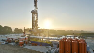
On land, extensions for four rigs in Saudi Arabia are collectively valued at $352 million, with contract durations ranging from five to 10 years, adding up to a total of 25 years. In Oman, the company extended contracts on three rigs worth a combined value of $50 million. Two rigs have also received two-year extensions while another was extended for nine months.
In Europe, the secured a new contract for a rig in Germany valued at over $10 million for nearly a year of work. In Pakistan, two new contracts worth over $20 million provide three years of activity.
Offshore, two contract extensions worth a total of six years and $87 million cover projects in Europe and Angola. In Norway, two contracts worth over $410 million add to the company’s backlog.