Completion-based velocity string solutions can help extend life of gas wells, maximize recovery
In Oman, new iterations of these solutions have supported evolving requirements for enhancing recovery in hundreds of wells
By Simon Leiper, Viking Completion Technology
Balancing energy demand alongside the impact of carbon emissions on global sustainability and net zero efforts is a challenge that everyone within the energy supply chain must consider carefully. There is a shared responsibility to produce hydrocarbons as cleanly and efficiently as possible.
With an increasing demand for natural gas, maximizing ultimate recovery and minimizing the resources required to achieve that goal is critical to achieving a better equilibrium. Thus, operating companies increasingly require a solution for liquid loading of gas wells that impacts or, in many cases, ceases production. As the industry considers the best way forward, the advancement and integration of velocity strings in extending the life of a well provides an alternative route for operators.
Evolving completion requirements
A velocity string is a remedial solution to an existing well – one that may have been completed several years prior to the requirement of a velocity string solution. It is suitable for diverse well requirements, as such varying challenges may often exist from well to well depending on how the well was originally developed and completed; the well’s surface infrastructure; and the availability of local services such as rigs, hoists, coil tubing, wirelines and expertise.
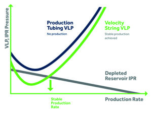
The velocity string theory is quite simple. By reducing the production string diameter, the velocity of the produced gas increases, and along with it, the fluid-carrying capacity allows stable production conditions to resume. This is demonstrated in Figure 1, which compares the vertical lift performance (VLP) curves of the liquid-loaded larger bore production tubing versus the velocity string VLP.
The production string diameter is achieved by installing and suspending a smaller-diameter string inside the existing production string. Despite the fundamentals of the velocity string theory being relatively simple, the successful application is not.
Velocity strings are a remedial solution for existing wells. Therefore, there is not a standard design of velocity string ready to be picked from a catalog.
With projects that integrate velocity strings, success requires a detailed review of the existing well design and any operational information related to the well to select the right solution for recompleting and extending the life of the well. Beyond this, other considerations like the local availability of services, rigs, coil tubing, hydraulic workover units, hoists, wirelines and flow control equipment are just as critical.
Velocity string designs
One of the simplest forms of velocity string is to run and suspend an inner string from a traditional tubing spool installed at the surface. These are typically coiled tubing-based or involve a simple jointed pipe string.
Conventional velocity strings installed in a hanger from a spool piece at the surface will require the tubing retrievable subsurface safety valve (TRSSSV) to be permanently locked out. These conventional approaches present a well control issue that may preclude the installation of a velocity string.
Specific issues relating to conventional velocity string installation are addressed and solved by integrating a completion-based design where all the velocity string equipment is installed into the well below the TRSSSV. Conventional rigs, hoists, hydraulic workover units, or coil tubing are among the deployment options.
The core piece of equipment required is the hydraulically set velocity string hanger packer that needs to run through the restriction in the TRSSSV, and then set in the tubing string below that will be a larger ID. Future decommissioning will require retrieval through the same restriction.
The varying combination of TRSSSV profiles, tubing string sizes, weights, material and pressure ratings require a wide range of specially designed packers that, with today’s focus on industry validation, will require testing to API 11D1 V0-R.
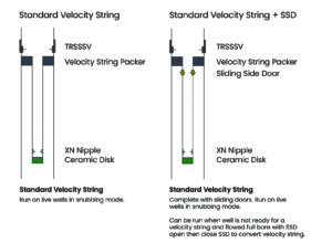
As illustrated in Figures 2 and 3, below the packer, tubing is suspended up to 5,000 m in length to provide the required production conduit to lift the well. Additional equipment such as sliding slide doors (SSD), nipple profiles and temporary plugging devices like ceramic disks may be required to facilitate operations – ranging from time of installation to abandonment.
In some cases, it’s necessary to suspend the well before installing the velocity string. This can be achieved by running a wireline set packer as part of a short BHA that acts as a plug until such time as it’s opened by accessing it through the velocity string.
For passing and retrieving through the TRSSSV, the same design requirements exist. Therefore, the design, development and testing of both packer types are typically performed in parallel to provide optimal design flexibility. This is critical when trying to remedy wells not originally designed with a future installation in mind.
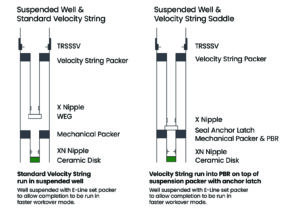
Two examples of completions with suspension strings are shown in Figures 4 and 5. Figure 4 features the velocity string spaced above the suspension string, and Figure 5 features a mechanical connection between the velocity string and suspension string.
A third option exists – sealing the connection and resulting in the isolation of a specific section of the well. The inclusion of an SSD in this isolated area allows for the effective management of different reservoirs or remedying integrity issues such as a failed liner top.
Case study: velocity string case well designs and considerations
For over a decade, Viking Completion Technology has pioneered completion-based velocity string solutions within the Oman region. These solutions have been pivotal in the ultimate recovery of hundreds of local gas wells. In the 10+ years since Viking first applied its velocity string solutions for operators in Oman, its team has adapted the equipment to suit evolving customer needs – with solutions now available in up to 7,500 psi and a V0 rating.
For a specific Oman-based operator, the evolution of Viking’s equipment was crucial in supporting the operational and technical progression over time. In the early stages of the contract, commencing in 2013, the specifications didn’t involve any particular validation requirement whilst the pressure differentials were low at approximately 3,000 psi. During the initial years of the 10+ year contract, this evolved into requirements for API 11D1 V2 validation and pressures of 5,000 psi.
Arriving in 2023 due to policy changes from the end user, the latest iterations of well designs featured API 11D1 V0-R packers and a 7,500-psi pressure rating. Within the energy industry, this amount of adaption and a high level of design variation, over a relatively short period, put this type of solution in the bracket of new or evolving technology.
Over the past decade, well designs have consistently evolved, resulting in new iterations to facilitate different requirements from the operator and simultaneously addressing lessons learned.
Some wells have been completed without introducing fluid during the completion phase, which required specific consideration of pressure differentials below the suspension string that may impact intervention operations, such as breaking the ceramic disk (plug) to open the well.
Wireline tool strings could be forced up the well, causing a bird’s nest and fishing operation if the situation was not properly managed. This was avoided either by the inclusion of equipment such as equalization valves or through wireline tool string design and operational sequences.
In some cases, for additional well control, fluid is introduced as an additional barrier. This creates the opposite scenario whereby a fluid velocity will occur over the tool string heading to the reservoir whilst gas migrates up the well over the tool string. For this scenario, Viking designed specific wireline tool strings that included a no-go, fluid bypass and tell tales to allow for the well to stabilize before pulling out of the hole.
Anticipating future requirements
Over time, as more gas wells are completed and existing wells age, the need for remedial solutions to extend production and maximize ultimate recovery will be increasingly common. Completion-based velocity strings provide the vital feature of maintaining the TRSSSV and have no impact on the surface infrastructure that can be challenging to modify, especially in situations where space is limited to increase the height of the wellhead or Christmas tree.
The number of variations of completion design that exist in the world are vast since there is no standard way to complete a well. It is, therefore, imperative to have access to a wide range of existing and proven specifications to make the process of designing a fit-for-purpose velocity string manageable.
Beyond that, the provider should have a track record of design, manufacture and installation of such systems to mitigate risks during execution of the work. Where a modified specification is required, suppliers with the experience of designing and validating new completion equipment to industry standards, such as API 11D1 and API 19AC, are critical.
Where geographically beneficial, equipment suppliers need to work closely with local service companies to deliver, to the end users, the completion equipment and longer-term support through life of well. DC