Gyro-while-drilling technology enables wellbore collision risk management in ERD application
Gyroscopic surveying system combined with advanced RSS helps operator to drill new well to access bypassed oil from aging Gulf of Thailand field
By Manchukarn Naknaka and Praisont Prasertamporn, Mubadala Petroleum; Adrián Ledroz and Jayaneethe Naranasamy, Gyrodata; and Kesavan Ramasamy, Baker Hughes
In complex oilfields with diminishing production values, accessing untapped reservoir areas is one method of improving overall field economics. Operators typically drill many wells in the same field, creating a risk to safety and production when attempting to drill a new prospect well near the existing ones. As the risk of wellbore collision increases, the value of drilling the well effectively decreases, and relying on MWD surveys opens the operator up to additional challenges with the quality of the survey data.
To combat this problem and improve the accuracy of wellbore surveys, the operator decided to pair a rotary steerable system (RSS) with a gyro-while-drilling (GWD) solution tailored to high-inclination wells.
Background
Mubadala Petroleum, a large upstream E&P company operating primarily in the Middle East and North Africa, Russia and Southeast Asia, was planning a well in the Jasmine field in the Gulf of Thailand. The field, which has been on production since 2005, is a complex oilfield containing multiple stacked sand reservoirs, largely comprising individual oil and gas water contacts.
One of the major challenges associated with this field is accessing the remaining bypassed oil. This is exacerbated not only by the geological conditions of the area but also the fact that the existing wells are aging and drilled closely together.
As such, the risk of wellbore collision in this project was significant. Mubadala Petroleum needed to drill the new well in close proximity to the existing producing wells to maximize production. However, due to platform slot limitations, the new well had to be drilled from a different platform.
This meant the new well would be an extended-reach drilling (ERD) well, with risk of collision with more than 40 neighboring wells. The well profile needed to be optimized to develop the undrained oil, but difficulties with directional drilling and the congested nature of the field made proximity challenges a major concern.
The consequence of a subsurface well collision could be an underground blowout, loss of well integrity or loss of production, which would have significant financial and safety-related consequences. To manage the ERD well with proximity challenges, the operator decided to utilize Gyrodata’s GWD90 system, which was designed for high-inclination scenarios. This was run in combination with Baker Hughes’ advanced RSS, the AutoTrak eXact high-buildup-rate RSS with LWD, to maximize technology impact and ensure achievement of directional drilling objectives.
Technology
Placing a gyro in a bottomhole assembly (BHA) and measuring the Earth rate as part of the drilling process was developed more than 15 years ago. The main purpose of these early tools was to provide azimuth and toolface orientation near vertical in areas where MWD tools were unable to provide reliable directional information due to magnetic interference.
As time went on, however, operators appreciated the time savings and safety advantages of GWD and pushed for tools that could be used at higher inclination.
Spinning-mass gyroscopes are the most commonly used type of gyro sensor for wellbore surveying. To achieve an adequate level of accuracy at high inclination with a spinning-mass gyroscope, however, it was necessary to remove and control changes in the biases and mass unbalance (the gravity-dependent bias).
An indexing mechanism allowed most of the gyro bias to be removed, though some residual errors might remain. Mass unbalance changes can also cause azimuth errors, and both grow with inclination, which means they had to be controlled to increase the inclination limit of the gyro survey tool. The typical two-axes system has an expected accuracy degradation with inclination and, at horizontal, is completely unreliable
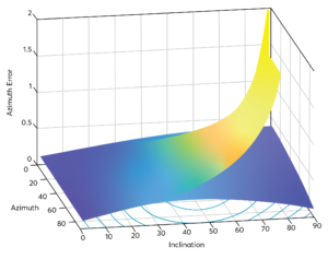
The GWD90, a gyroscopic surveying system comprising three orthogonal gyro axes, enables gyrocompassing at any inclination, substantially reduces azimuth uncertainty versus the traditional two-axes system (Figure 1), and provides comprehensive quality control (QC). The additional axis is aligned with the z-axis of the tool and is compensated by the indexing mechanism, with QC based on comparing theoretical values of the Earth rotation rate and latitude with those computed by the gyro.
The system also incorporates more robust sensors, permitting drilling in ERD applications and harsh-environmental conditions without the need to pull out of hole and replace the survey tool. This was critical for the operator on this project.
The system was incorporated inside a collar. BHA placement was flexible because the system was not affected by magnetic interference and had feed-through capabilities. The system sent survey data, QC information and tool status to the MWD tool, which then transmitted the information to surface using mud-pulse telemetry.
Stationary surveys were acquired during connections, limiting movement in the environment and minimizing survey time and impact to rig operations. The survey cycle started when the MWD tool detected no-flow and transmitted that information to the GWD system, initiating a gyrocompass process.
QC procedures
The GWD system was subject to a series of rigorous QC tests. This was not only important to align the system’s performance with the operator’s, contractor’s and international standards for wellbore collision avoidance but also to ensure that risk was managed and mitigated.
Comprehensive QC is the backbone of the system’s success, as achieving the objectives typical of gyroscopic surveying is not possible without a reliable and accurate system.
QC procedures were broadly broken up into eight stages as discussed below.
Stage 1: Calibration
During the calibration process, tool readings are monitored over the temperature range and compared with calibration stand positioning. A pass/fail criteria based on the uncertainties of the error model was established, and only tools that passed are allowed to go to the field.
Stage 2: Call-out sheet
All job details are captured on the call-out sheet, including well profile, pressure, temperature, AC scan and so forth. These details are verified as correct and approved by an appropriate representative.
Stage 3: Standalone system test
The system is tested to ensure tool functionality. Once this is done, a complete system test is performed between the host MWD system and the GWD system to ensure communication and functionality. In addition, a base roll test is performed, and all QC tolerances must be within specification before the system is loaded out to the rig site.
Stage 4: Rig-site systems test
After arriving at the rig site, the survey specialist carries out a check of all equipment and tool functionality and verifies that the equipment is in good working condition before the survey begins.
A pre-job roll test is performed, with additional checks for transit damage and function checks for both electronics and mechanical running gear. Afterwards, a document is compiled to be reviewed and approved by the operations support group before the BHA is made up.
Stage 5: Rig-site data collection
When the BHA is made up, a shallow hold test is performed to ensure the GWD system communicates with the MWD equipment. A basic gross error check is also performed before tripping in and starting drilling. The GWD surveys processed downhole and together with the survey QC and status words are sent to the MWD tool, with only surveys that meet the established quality standards used as definitive results.
Stage 6: Rig-site post run
After performing a comprehensive tool check, any discrepancies on the tool reading (exceeding tolerances) or tool damage are reported, and the tool is tagged for further action.
Stage 7: Base post-run check
All tools are tested to ensure that they are still within tolerances. A post-job roll test is performed and used as assurance and confirmation of sensor calibration.
Stage 8: Base equipment return
After confirming the results of the roll tests, the equipment asset numbers are verified against a pre-deployment inventory list, and the equipment is inspected and verified as fit for purpose and ready to be used on the next deployment.
Case history
Mubadala Petroleum needed to drill the ERD well efficiently and without risk of wellbore collision. It was critical to avoid collision with any of the other wells while placing the new well in a way that would maximize hydrocarbon recovery factors. To accomplish drilling the fragile wellbore in such a congested area, the new well required an S-shaped trajectory with a long tangent section at an inclination of 78°.
The operator chose the GWD90 system not only to ensure that wellbore collision was avoided but also to eliminate the threat of magnetic interference corrupting the MWD survey readings.
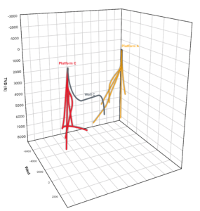
Jasmine A platform’s drilling slots had been used to maximum capacity. Because adding more slots was not possible, the operator decided to drill the ERD well from the Jasmine C platform to access resources in the Jasmine A block. See Figure 2 for a 3D view of the ERD well trajectory from Platform C to Platform A.
The new well’s trajectory was designed to come close to a previous exploration/appraisal well, but the existing offset well lacked the survey data necessary to effectively model the ellipse of uncertainty to the level of accuracy required to safely drill the ERD well. Magnetic interference was a significant concern given the field’s lithology and the high concentration of nearby wells, and Mubadala Petroleum was not willing to take the risk of drilling the ERD well under such conditions.
The risk of collision was appraised with the convergence of the two wellbores, with the separation factor – that is, the ratio of the center-to-center distance divided by the sum of the survey uncertainties – being 0.69 between the new well and the oil producer well. Any separation factor below 1.0 is generally unacceptable by both contractor safety rules and operators due to the high likelihood of collision as the ellipses begin to overlap.
Accordingly, the well could not be safely drilled in such a scenario. The high inclination of both wells amplified the risk of drilling the ERD well unsuccessfully.
“The project was the first drilling application in the Gulf of Thailand combining the GWD90 system with an advanced RSS.”
To solve the problem, Mubadala Petroleum decided to implement the GWD90 system in the 8 ½-in. BHA to reduce positional uncertainty and the risk of wellbore collision. Specifically, the system was used to reduce position error and increase the accuracy of wellbore placement in combination with the AutoTrak eXact RSS for precision drilling control. Using the GWD system increased the separation factor from 0.69 to 1.00, meaning the ellipses of uncertainty no longer overlapped and the risk of collision was greatly reduced.
The operations support team developed a collision-monitoring flowchart, which was used in the execution phases of the project to eliminate miscommunication while drilling the well. The system provided real-time surveys to a total depth of 8,945 ft and a measured depth of 10,076 ft in one run, surveying to a maximum inclination of 78° in the 3,780-ft tangent section.
The project was the first drilling application in the Gulf of Thailand combining the GWD90 system with an advanced RSS. Overall, using GWD instead of MWD and in combination with the advanced RSS resulted in increased ROP, improvements to well delivery time, reductions in drilling costs, and a better-placed wellbore in line with the operator’s plan to drill previously impossible prospects.
Based on the success of this project, Mubadala Petroleum has already begun to implement GWD services on several other wells in the region. The need for companies to reduce the risk of wellbore collision in fields with a high density of wells will only increase as the oil and gas industry continues to evolve. GWD systems represent one way to improve the accuracy of wellbore placement versus traditional solutions, deployed by forward-thinking operators willing to adopt innovative technologies to drill better wells. DC
GWD90 is a trademark of Gyrodata. AutoTrak is a trademark of Baker Hughes.


