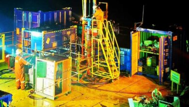
Geothermal development calls for directional drilling tools with higher temperature capabilities
New design approach with circular shaped circuit board, mounted in stack perpendicular to tool axis, aims to increase thermal resistance
By John Clegg, Hephae Energy Technology
Next-generation geothermal systems will allow geothermal energy to be exploited in hot, dry rocks by creating artificial reservoirs – in the same way as unconventional oil and gas wells created artificial reservoirs earlier this century. Next-generation geothermal systems can include so-called enhanced geothermal systems (EGS) and advanced geothermal systems (AGS), but regardless of the principle used to design the well, two key characteristics will define almost any such system.
Firstly, they will require accurate well placement to optimize production, and most such systems will use horizontal wells. To achieve this, techniques developed for the oil and gas industry can be imported using tools like measurement while drilling (MWD) and rotary steerable systems (RSS).
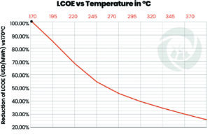
Secondly, in order to make them economically viable, their drilling costs need to be minimized and the value of production maximized. The use of MWD and RSS can help to reduce drilling cost, but in order to maximize the value of production, the temperature of the formation drilled needs to be as high as possible. Modeling using the US Department of Energy’s Geothermal Electricity Technology Evaluation Model shows that, if other variables are normalized, the impact of temperature on the levelized cost of electricity (LCOE) is significant (Figure 1).
The graph shows that, when compared with 170°C, an increase in temperature to 210°C will reduce LCOE by approximately 25%. Increasing the temperature rating further to 300°C can reduce LCOE by 65-75%. Therefore, there is significant incentive to develop tools that are capable of drilling wells with increasingly higher temperatures.
The oil and gas industry has made an excellent job of developing tools to work in high-temperature oil and gas wells – the first commercial MWD system, in 1978, was rated to 85°C, and the first 175°C-rated MWD was released by 1996. In less than 20 years, the industry had gained 90°C of capability and the ability to drill the majority of oil and gas reservoirs. Unfortunately, since then, the process of increasing temperature capability appears to have stalled. The industry has seen a few tools capable of 185°C and a notable few that will work at 200°C, but there is nothing rated for higher temperatures.
One set of solutions that is often suggested is the use of insulated pipe, or drill pipe coated with a thermally insulative coating, together with chillers to cool the drilling mud before it is pumped into the well. It is sometimes argued that these technologies will be enough to keep the MWD and RSS cool. These techniques are helpful, but only while the mud is flowing. When circulation stops – for example, while making connections and, most importantly, while running in hole – the sensors and electronics inside the MWD and RSS can very rapidly reach the same temperature as the surrounding formation.
This can be a significant problem while running in hole, whereby the MWD has to be periodically cooled by mud flow from the surface before running a little deeper until it gets too hot again, and repeating the process – perhaps many times. This is known as “staging in” and can add many hours or even days to drilling a section. Additionally, if there is a directional motor in the string, the extended period of off-bottom circulation can cause significant damage to drill bits and other BHA components.
The optimum solution is most likely a combination of these technologies with higher-temperature sensors and electronics. But how can these higher-temperature tools be created?
Technology advances in respect of the construction of components, sensors and integrated circuits mean that these items are increasingly capable of handling high temperature – but this is not enough by itself. To make an electronics assembly survive at the temperature downhole, three key requirements must be met.
Firstly, and perhaps most obviously, the assembly must be protected from the external borehole temperature. In principle, Dewar, or Thermos, flasks can be used to protect a tool from the external environment, but they can also prevent any internally generated heat from escaping.
This leads to the second key requirement. Electronic components can be very effective at generating their own internal heat – as anyone who has ever used a mobile phone or a laptop will know. So, although high temperature resistant components should be selected, they must also be protected effectively from themselves, by taking heat away from all components on the board.
The third key requirement is that any rejected heat from electronic components must be taken to a place where it will do no harm. The laws of physics prohibit heat being destroyed, but it can be moved. For lower temperatures, it might be enough to conduct the heat into a pressure vessel so that it can be carried away by drilling mud flowing past the tool. For higher temperatures, other strategies may be required, including cooling technologies. Ideally, a board design and mounting scheme is needed that can work in either case.
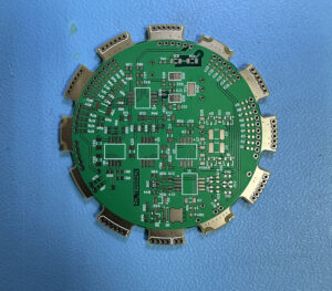
This requires a departure from the long, thin and rectangular boards typically used to build MWD and similar tools and which generally run the length of an electronics chassis or insert. Figure 2 shows an alternate approach.
This circuit board is not long and thin, but rather circular in shape and designed to sit in a stack whereby it is mounted perpendicular, not parallel, to the axis of the tool. The circular shape allows heat to be easily moved from a component to the edge of the board. The board is sufficiently small that no individual component is far from its edge, and the circular shape of the boards promotes radial transport of heat, from the center to the edge, as the cross-sectional area for flow increases. Therefore, the effective thermal resistance reduces as heat flows from the center of the board.
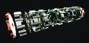
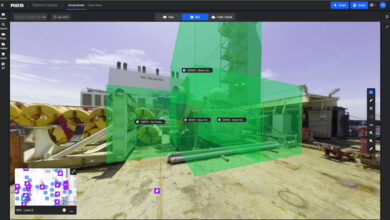
When the heat gets to the edge of the board, the design of the PCB stack ensures that it is moved away quickly. Figure 3 shows the stack.
As can be seen from the image, each board is surrounded by a ring, which is made from a thermally conductive material. When assembled into a stack, these rings form a “thermal superhighway” that allows heat to be removed rapidly and to flow axially either into a connection with a pressure vessel in contact with cooler drilling mud, or to a cooling system.
In the absence of careful thermal design such as this, the temperature of the die (the wafer comprising transistors) inside an integrated circuit could be 20°C to 40°C higher than the ambient temperature. Modeling has shown that this approach can reduce the differential to about 5°C, giving the design significant thermal advantage.
The stack is built up as an “endoskeleton” – although all components are protected inside of the rings, test and wiring points are available and accessible on lugs that protrude beyond the outside of the rings. This significantly simplifies repair, assembly and test, as well as enhances reliability of wire connections between boards. To date, all assemblies have undergone extended duration testing while exposed to temperatures up to 230°C. All boards were operational to 220°C, and everything survived extended periods of exposure at 230°C. This indicates that a tool specified to 210°C is very feasible. This effectively proves the physics of being able to operate at temperatures above 200°C. None of the integrated circuits used suffered high-temperature problems such as excessive leakage or capacitance. The oven tests have paved the way for Highly Accelerated Life Testing (HALT) under a combination of shock and vibration.
Unlike typical oil and gas tool tests, these tests will be conducted under extended durations with imposed vibration up to 30G RMS. This is 50% higher than the level normally used to test oil and gas tools (20G) because geothermal wells are expected to see higher levels of shock and vibration on account of being deeper, in harder formations, and with higher coefficients of friction between formation and the drill bit and/or BHA.
At the time of writing, all boards and assemblies tested have passed extended duration testing at 230°C and 30G, in addition to multiple shock tests at 1000G.
In conclusion:
- Geothermal wells need to be drilled accurately and will benefit significantly from being placed in high-temperature formations.
- In principle, the oil and gas industry has the equipment needed to drill these wells, but unfortunately the development of temperature capability has stalled.
- Mitigating technologies can be part of the solution, but are limited by the need to circulate fluid in order to be effective and do not help much while making connections and particularly while running in hole.
- Three key requirements for high-temperature electronics are to:
-
- Protect the assembly from the external borehole temperature
- Protect components from themselves, efficiently and quickly remove the heat that the components generate internally
- Take the rejected heat from the components to where it will do no harm
- A stack of circular boards can meet these conflicting requirements
Initial oven testing was successful at temperatures up to 200°C, and HALT testing shows great promise for operation above 200°C. DC
This article is based on a presentation at the 2025 IADC Geothermal Drilling Conference, 25-26 March, Vienna, Austria.