Engineering, simulator testing help to integrate automated well control into rig control system
Process involved both rig and downhole simulators, as well as using the integrated system to control a fully equipped test rig
By Bryan Atchison, Safe Influx, and Fraser Dunphy, Finesse Control Systems
Automated well control performs all the tasks traditionally performed by the driller to identify an influx, and then controls the drilling and blowout preventer (BOP) equipment to safely shut in the well. Automation has been proven to deliver benefits in efficiency, reliability, repeatability, quality control and safety across a spectrum of industries. By carefully considering all possible scenarios in advance, identifying the key parameters to be monitored, considering the appropriate steps to be taken in each scenario, then programming machine controls to deliver these results every time, automation takes the pressure off of the machine operator to take the right decisions in the heat of a crisis. Applying these principles to well control in a potentially life and death situation will free the driller to concentrate on managing the situation rather than having to focus on controlling various pieces of machinery to step through a critical sequence of actions.
Multiple industries have proven that, with the right sensors, a critical situation can be identified by a machine controller more quickly and reliably than by the best machine operator. Further, a well programmed machine control system will complete a sequence of critical actions more quickly and efficiently than a human operator. Hence, the potential to minimize the size of an influx and deliver the well to a safe condition using automated well control is greatly enhanced.
The benefits of using the logic of automated well control integrated with the tools of the original equipment manufacturer (OEM) are significant. Further, from a human factors perspective, integrating the logic into the OEM control system removes the requirement of additional screens, alarm systems and equipment, which has tangible benefits for the operating environment of the driller.
Safe Influx and NOV recently developed this process and then executed and successfully tested the integration.
Integration process
A progressive risk exposure and risk management approach was undertaken. This ensured the integration of these technologies was implemented with minimal or zero additional risk to process or personnel. This is always a necessary focus when modifying software in a critical process, particularly in the real world when controlling equipment in heavy industries. This addressed potential additional risks from enabling systems to communicate with each other automatically, creating additional automation and human interface risks.
An integrated project team was appointed in the two organizations with the commensurate skill sets required. Project management systems were used to execute the project, including: a clear project scope, a project manager and team members, weekly project meetings, and project meeting minutes to capture decisions, actions and information requests. Meetings across different countries were conducted using videoconference tools.
The project plan was developed to manage the success of integration by using recognized engineering and simulator testing techniques to establish safety and functionality and to identify any bugs or clashes. Once simulator testing was proven successful, migration into the real world was possible by installing the system on a rig test facility.
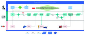
A critical element of the integration process was the development of a robust input/output register, providing the appropriate interface addresses for the three computer systems to communicate with one another effectively.
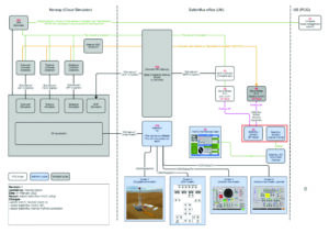
Figure 1 shows the system topology that was developed.
Simulator integration and results
A hybrid simulator test rig was developed. The rig simulator and downhole simulator were provided by the OEM. Access and control of the simulator online precluded the requirement to mobilize equipment and personnel to a physical location. The time and cost advantages of remote operations were significant.
The automated well control system was validated with physical signal simulation rather than software simulation. The unit was placed in a test room with several screens providing all the required information to conduct the full simulator testing.
A structured program was developed to verify system checks, power up, communications, integration, scenarios and test procedures. Multiple combinations of variable settings, equipment combinations and scenarios were used attempting to identify any potential clashes while monitoring the functionality of the automated well control system. All the tests were video recorded, and a written log of main actions and observations was recorded.
The objectives of the test were to establish and test the interface arrangements to ensure that:
1. The Safe Influx automated well control system can be integrated with the rig operating control systems.
2. The integrated system successfully functions and completes the automated shut-in sequence on detection of an influx.
All objectives for the simulator integration were achieved
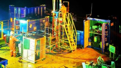
Following a management review, the project team progressed to the next phase of integration involving the use of the integrated system to control a fully equipped test rig based in Texas.
Test rig integration and results
A revised project team was established, including the appropriate skill sets from the test rig. Similar project management tools were then employed to migrate the test from the simulator environment to the real-world environment. Some alternative, more effective, communication protocols were required due to the direct connections with the rig and BOP control systems. The principles of topology that were established in the successful simulation tests were followed. Several project documents were created to document and manage the test rig integration. These include rig test procedure, observation log, action register, integrated system one-line diagram, input/output register, automated well control logic diagram, rig installation plan, training material and minutes of rig safety meetings.
The rig data log was used to facilitate documentation of all tests.
The objectives of the test were to establish and test the interface arrangements to ensure that:
1. The Safe Influx automated well control system can be integrated with the rig operating control systems for an actual rig, including functioning the BOP equipment.
2. The integrated system successfully functions and completes the automated shut-in sequence on detection of an influx.
All objectives for the test rig integration were achieved.
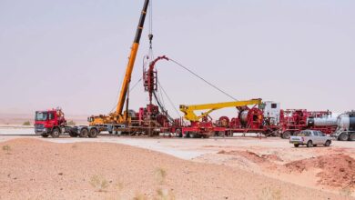
Following the successful test rig integration, management review and subsequent approval, the project proceeded toward an extended rig test and demonstration to potential clients.
Extended test, demonstration and results
When a suitable rig test slot was established, the project planning commenced to enable a two-week testing and demonstration exercise to be conducted. The system was successfully demonstrated to approximately 40 industry personnel from approximately 12 operator and drilling contractor companies.
The demonstration involved a three-stage program of introduction and site briefing, rig demonstration and feedback session.
During the introduction, the details of interactions with three processes running in parallel was discussed using Figure 3.
The automated well control system and integration into a rig control system were successfully demonstrated to all attendees.
Results and conclusions
A structured engineering approach to integrating automated well control with a rig control system was developed and executed. A series of tests with progressive risk exposure provided the project and management teams with sufficient evidence, developing confidence at each stage to progress with the implementation process. Throughout the process, there were no incidents, accidents, equipment damage or personnel injuries. A rigorous approach to project management, capturing lessons learned, observations and feedback has provided the integrated team with invaluable knowledge to introduce automated well control to the industry.
Safe Influx automated well control system
The automated well control system was developed for Safe Influx using a Siemens PLC system by Finesse Control Systems. It has a dual redundant central processor unit (CPU) providing a high-availability platform, where each CPU monitors the other continually and, in the event of a failure, the good one carries on looking after the process. This minimizes risks and ensures the system will be good to go when needed.
Additionally, Safe Influx opted to utilize a safety-rated PLC that has been independently validated as capable of being programmed using Siemens Standard programming blocks to give minimal risk of failing to an unsafe condition. This has provided for the possibility of integrating with similarly high-integrity equipment from OEMs where that is available to achieve a certified (Safety Integrity Level) SIL2 or SIL3 safety process.
Due to not having certified OEM equipment available, this level of integrity for the system has yet to be developed. However, the choice to build the system with such a processor ensures the Safe Influx automated well control PLC will not be the weak link for delivering a safe shut-in.
When integrated with a cyber rig control system, the automated well control receives information from the cyber rig and sends instructions back to the cyber rig control CPU over a data link and instructs the BOP CPU when to close over a similar data link.
The automated well control CPU contains the logic to monitor the data provided by the existing rig control systems to detect an influx and validate what is happening. Then, depending on the positions and operating status of the various pieces of equipment, its logic selects the appropriate course of action from predefined options.
Over the data link, it sends a series of instructions to the rig control systems. These instructions act in parallel with the existing signals from the driller’s controls, hence all the other automated safeguards remain intact on the drilling systems.
The automated well control system is, in effect, acting as driller’s assistant, doing what the driller would previously have done.
This removes the pressure on the driller to remember the sequence of steps and proceed through them in the heat of the moment with all the distractions of the operation around him.
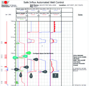
The machine will not be distracted or caught off guard; it will always do what it has been programmed to do: stop drilling, space out, stop top drive, stop mud pumps, and close the preselected BOP. DC