Dual-gradient system evaluation highlights key high-risk issues
Study focuses on subsea integration, fluids discharge, maintenance, pump impact on LWD
By Bibek Das, Marco Figoni, Jorge Ballesio and James Bond, American Bureau of Shipping
The offshore industry frequently develops novel applications and processes that have no track record in the environment being proposed. These concepts may differ significantly from existing designs such that the guidance encompassed in current prescriptive rules may not be directly applicable. In such cases, risk-informed approaches are adopted to aid decision-making.
Dual-gradient drilling (DGD), a variant of managed pressure drilling (MPD), is an example of such a technology. This article provides an overview of the studied DGD system and equipment, as well as a hazard identification and risk assessment methodology developed in accordance with the ABS Guidance Notes on Review and Approval of Novel Concepts. Brainstorming sessions with engineers from drilling, controls, subsea, maintenance and class have resulted in recommendations that have been valuable in reducing and managing risks to as low as reasonably practicable (ALARP) levels.
A functional failure modes effect and criticality analysis (FMECA) was conducted on the DGD system. The assessment shows the significance of dealing with failure issues that can lead to potential discharge of wellbore fluids to the sea, as well as the importance of maintenance, inspection and personnel training. Several topics are identified as requiring further research.
Project Background
One challenge in deepwater drilling is the narrowing of the pore pressure/fracture gradient margin, mainly due to the decrease of fracture gradient as water depth increases. This means more casing strings, shallow casing points, longer and heavier drilling risers and bigger and more expensive rigs. To date, several variants of MPD systems have been used. This article focuses on DGD achieved by mechanical lifting, which is a new technology as far as operation and maintenance data are concerned.
When developing classification and safety requirements for a novel technology, ABS adopts the following evaluation methodology:
1. Develop an understanding of the concept;
2. Identify the novel aspects of the proposed design;
3. Identify the hazards and safety concerns arising from the concept and from the specific novel features;
4. Identify existing marine and offshore requirements and standards and conduct a gap analysis;
5. Use the gap analysis to identify those areas of the design for which no relevant marine standards currently exist; and
6. Apply first principles design and risk methodologies to assess the risks.
This approach has been followed in the evaluation of the DGD concepts that were presented to ABS in request of Approval in Principle (AIP). When developing rules, ABS places paramount importance on promoting safety of life, property and the natural environment. Thus, the primary focus of this article is on the safe application of DGD equipment and not the optimization of the design, with respect to efficiency or return on investment.
FMECA and “what-if” analyses are carried out on the DGD system and its equipment at a functional level to determine safety and environmental risks. The next step, which is outside the scope of this article, is to determine possible measures to eliminate, mitigate or reduce the identified risks.
DGD Overview
As new reserves are explored in ultra-deepwaters, the capability limits of current risers are being approached. The long riser strings required for greater water depths may experience significant stresses due to vibration. Deepwater drilling involves a narrower drilling window due to deepwater overburden, where a very narrow margin between pore pressure and fracture pressure profiles exists. Thus, maintaining the hydrostatic pressure on the mud line becomes a challenging design and serious operational issue. The alternate technology is to use a riserless mud recovery (RMR) and DGD system.
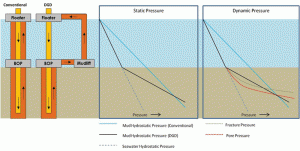
Dual gradient uses two hydrostatic gradients – the seawater gradient from sea surface to seafloor to manage the borehole and the mud gradient from the sea floor to prevent the borehole from collapsing and removing cuttings from the borehole (Figure 1). Thus, the mud return does not go through a conventional large-diameter drilling riser. The separate mudlift system uses a return line that is powered by subsea pumps.
In a static condition, the bottomhole pressure is balanced by the hydrostatic pressure. In dynamic condition when the mud is circulating the hole, the bottomhole pressure is a function of hydrostatic pressure and the annular friction pressure.
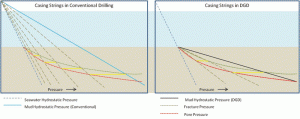
The two limiting pressure gradients are pore pressure and fracture pressure. As seen in Figures 1 and 2, the DGD system provides a larger drilling window compared with a single fluid conventional system, thus requiring fewer casing strings.
With DGD, the bottomhole pressure is achieved using a combination of two fluids – seawater and heavy mud. The drilling rig can be said to be effectively on the seabed as the water depth overburden is balanced by the seawater line gradient (Figure 2).
This helps to better manage the margin between pore pressure and fracture pressure, significantly reducing the number of casing strings that would have been required if a single fluid (mud) were used to reach the bottomhole pressure and avoid lost circulation.
The DGD system requires additional equipment subsea, as well as on the rig. Thus, two system integrations must be considered. One is the subsea integration involving pump, drill string valve (DSV), subsea rotating diverter (SRD) on the BOP, etc. The other is the rig integration involving surface pumps, dual trip tanks, strengthened cellar deck, additional controls, etc. The latter is out of the scope of this article.
Offshore Regulatory and Safety Regime
Offshore regulatory regimes focus on safety and are applied through many layers, ranging from the international level, which facilitates and regulates global safety goals, to class societies that develop and publish rules and guides for structural and mechanical integrity of the complete marine and/or offshore structures, to industry codes and standards that also provide requirements for mechanical integrity of specific equipment or components.
To protect the interests of their territorial waters, local jurisdictions also institute regulations to ensure safety. Finally, the maritime vessels or offshore structure owners/operators also have established their sets of technical, operating and maintenance requirements to ensure safe operation and protect their capital assets.
Novel Concept Approval Process
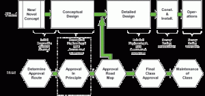
The ABS review of novel concepts follows three stages: (1) Conceptual design and AIP; (2) Detailed design and construction, and issuance of ABS class approval; and (3) Operations and maintenance of class. The AIP stage deals with the risk-based approval process and requires submittal of conceptual engineering and risk assessment studies. The final class approval stage requires submission of detailed risk assessments. Figure 3 shows the process that ABS and the client follow to achieve these milestones.
The ABS Guidance Notes describe the use of qualitative and quantitative risk assessment tools to identify the hazards and assess the risks introduced by the novel features, operability and any interface issues with other systems. The tools commonly employed range from qualitative hazard identification tools (for example, What-If, HAZID, HAZOP, FMECA), a fully reliability-based approach to demonstrate the functionality and achieved margins of safety, a deterministic approach to assess consequences of failures, or a semi-probabilistic approach to assess the sensitivities and variability of key design parameters.
The Guidance Notes also discuss a comparative risk assessment (qualitative or quantitative) where the risk levels are compared with risk levels of other systems instead of absolute criteria.
The final class approval stage requires submission of detailed risk assessments, which may be supported by tests. The detailed risk assessments are intended to quantify risk and uncertainties in more detail for those hazards identified as high risk in the conceptual risk assessment during the AIP stage.
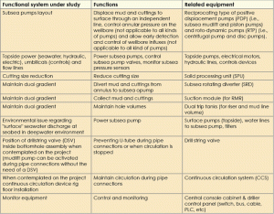
FMECA for DGD system
A failure mode effects analysis (FMEA) is a structured approach for identifying means of failure and the effects on a “local” and “global” basis. The objective is to determine whether a failure mode can occur, and if so, whether an unsafe or inoperable condition could result.
An FMECA is an extension of the FMEA and includes a criticality analysis, which is used to chart the probability of failure modes against the severity of their consequences. The result highlights failure modes with relatively high probability and severity of consequences, allowing a design improvement (or remedial) effort to be directed where it will produce the greatest value. The criticality ranking may include the failure detection capabilities present in the design.
For the evaluation of DGD equipment failure mode criticality, severity ranking was done on a 1-to-10 scale based on the safety and environmental implications and the downtime incurred before getting back into operation. The occurrence frequency was ranked on a 1-to-10 scale based on the expected failure frequency.
A limiting value of one failure in five years was assumed as the worst frequency. This assumption is based on the planned API 53 standard, which states, “At least every five years, the well control system components shall be inspected for repair or remanufacturing, in accordance with equipment owner’s PM program or the manufacturer’s guidelines.”
The failure detection capability was ranked on a 1-to-10 scale based on the available design controls and maintenance tasks available to predict the failure. An FMECA study performed during the design phase identifies the equipment and systems to which the maintenance activities should be concentrated during the development of a preventive maintenance programs (PMP).
At different stages of the operational life, an FMECA would also identify the failure history observed for the equipment and thus help in updating the maintenance philosophy and procedures. FMECA further helps in identifying functional failures and avoiding any single-point failures.
An FMECA study can be performed by a “functional approach” or a “hardware approach.” The functional approach is used to analyze the system and sub-system effects. This approach to FMEA was adopted for the study of DGD. These approaches help in tying the equipment to functional failures and to avoid single-point failures.
In the hardware approach, equipment components are represented in a block diagram, and the theory of operation and assumptions are written down. The FMEA following a hardware approach will be a detailed analysis down to each component level. This approach helps in detailed spare-parts analysis, updating preventive maintenance programs, etc. However, a greater level of detail for the equipment, operation and maintenance plan should be present for this type of study.
The functional-level FMECA study for the dual-gradient system identified the following:
• Credible failure modes applicable to each equipment item or grouping of equipment;
• Effects of the failure on overall operations and, where applicable, local and overall effects on the drilling unit;
• Foreseeable causes for each failure mode;
• Safeguards in place to detect, prevent or mitigate each failure;
• Recommended actions to address failure modes that, as judged by the FMECA team, are not adequately safeguarded; and
• Criticality rankings for each failure mode.
Some of the functional failure modes assessed during the FMECA study were:
• No seawater to power the mudlift pump or reduced flow due to clogging upstream;
• Loss of control on subsea pump hydraulic valves (only reciprocating type of PDP);
• Subsea pump hydraulic valves malfunction (only reciprocating type of PDP);
• Total loss of mudlift pump performance;
• Reduction of mudlift pump performance (degraded mode of operation);
• Subsea pump installation integrity compromised;
• Subsea pump valves partial or total obstruction (only reciprocating type of PDP);
• SRD unable to divert mud and cuttings to subsea pumps;
• Drill string valve malfunction; not closing during pipe connections or circulation stop;
• Drill string valve malfunction; remaining totally or partially closed after pipe connections at circulation restart and/or during drilling;
• Subsea pump valves plugged (only reciprocating type of PDP);
• Subsea pump plugged by cuttings;
• SPU plugged by cuttings;
• Subsea pump stops working;
• Reduced flow volume or no fluids coming from suction module (SMO);
• Fluctuations and/or reduction on subsea pump output (centrifugal pump);
• Stop of flow through subsea pump (centrifugal pump);
• Fluctuations and/or reduction on subsea pump output (degraded mode; only piston pump);
• Cross-sectional area reduction of subsea pump suction line;
• Partial or total subsea pump suction line fluid leak;
• Partial or total subsea mud return line fluid leak;
• Partial or total plug of SMO bowl by hydrates;
• SMO instability due to bad installation;
• Subsea pump induced pressure pulsation in piping/lines with cyclic stress inducing fatigue with eventual lines connection failure (only reciprocating type of PDP);
• Subsea pump impeller failure (centrifugal pump);
• Partial or total loss of the subsea pump monitoring sensors;
• CCS pipe ram activation failure;
• CCS blind ram activation failure;
• CCS chamber pressurization failure;
• Mudlift pump discharge of surface seawater layer to deepwater environment causing pH, oxygen and nutrients changes around wellhead; and
• Excessive noise around wellhead affecting deepwater marine life.
What-If Analysis
A “What-If” analysis is a brainstorming approach that uses broad, loosely structured questioning to postulate potential upsets that may result in mishaps or system performance problems, and ensure that appropriate safeguards against those problems are in place. This technique was used to supplement the FMECA study and to cross-check if possible failure modes and deviations have been addressed and the safeguards identified. For the DGD system, the following set of potential problems that could arise was generated using qualitative descriptions:
• What if mudlift pump stops working?
• What if seawater supply to the mudlift pump stops but hydraulic valves is still working?
• What if subsea pump valves synchronism is uncontrollable?
• What if one or more subsea pump valves stop?
• What if subsea pump starts to show low performance?
• What if subsea pump completely loses its performance?
• What if subsea pump valves are blocked?
• What if no fluids are coming from subsea pump suction line?
• What if SPU (when present) is plugged by cuttings?
• What if subsea pump installation is compromised?
• What if the mud return line breaks?
• What if the U-tube effect cannot be controlled?
• What if subsea pumps’ monitoring/control sensors fail?
• What if CCS fails during a pipe connection?
Technology Evaluation
Based on the evaluations and the reviews of the design concepts, the authors have identified the following elements, including typically associated types of hazards, as posing the greatest risks to life, property and the environment in the drilling application of the DGD system.
The hazards related to accidents such as uncontrolled blowouts and emergency disconnect procedures are out of the scope of this article.
Wellbore fluids discharge to sea
Compared with a conventional “pump and dump” system, DGD allows the use of drilling fluids with higher density and more appropriate chemical composition. But the risks related to discharge of wellbore fluids (i.e., combination of drilling fluids, cuttings and, when present, oil and gas) become higher. From this perspective, any leak on the return system from the wellhead to the surface can have a direct impact on the environment. The most critical situation is the one where a physical barrier (e.g., blowout preventer and drill string valve), used to preserve the wellbore integrity, is not present on the system and the leakage happens between the wellhead and subsea pump.
An example of such a critical situation is the riserless mud recovery (RMR) system used to drill the top-hole sections where only an SMO is installed on the seabed. The top of the SMO is composed of a bowl where wellbore fluids are in direct contact with the seawater. During normal operations without the presence of gas, those fluids are not mixing with seawater due to the density difference between them, and they are kept inside the bowl by the action of the subsea pump flow.
It was identified that there can be discharge of wellbore fluid and cuttings to the sea from the SMO bowl caused by:
• A cuttings-generated obstruction (or plug) of the subsea pump and/or the line from the bowl to the pump;
• An unplanned subsea pump stoppage due to a lack of power or umbilicals failure;
• A mechanical failure of subsea pump due to vibration, cavitation, erosion corrosion, wear of the rotating parts (when applicable), pressure pulsation and stress fluctuations on pump impeller;
• A pump blockage due to an excess of gas inside the pump (i.e., “gas lock,” in the case of centrifugal pump);
• SMO loss of stability due to poor installation or caused by seabed subsidence, shallow hazards, seabed liquefaction, underground blowout;
• A rupture in line (or connection) from SMO and subsea pump (in this case, the leak will be at SMO bowl and at rupture point); and
• An overpressure not controllable by subsea pump flow.
Other DGD configurations different from the one that was evaluated can also have accidental discharge of wellbore fluids to the sea:
• After a loss of containment of a subsea pump component;
• After a loss of containment of SRD (when present) and/or SPU (when present);
• After any loss of containment of return line and/or connections from wellhead to surface;
• After a loss of containment of mudlift pump elastomer (or elastomers), the failure can put wellbore fluid and cuttings in contact with the seawater used to power the pump. This water is normally discharged to the sea, and the seawater will be contaminated with fluid and cuttings; and
• After a loss of containment of the riser between the BOP and the subsea pump. This can happen in a post-BOP section when subsea pump is not close to the seabed and part of the riser act as return line.
On all DGD system configurations, when a leakage happens on the section between the wellhead and the subsea pump, backpressure will be applied to the wellbore and, without the presence inside the bottomhole assembly (BHA) of a DSV (or with a DSV damaged), the backpressure will continue even after a stop in circulation, until equilibrium is reached. This U-tube effect will also appear in a normal pipe connection with all pumps off, including subsea pumps, if a DSV is not installed or is damaged. This situation highlights the importance of a reliable DSV as an additional physical barrier to enhance the safety of the operations.
Maintenance and Inspection of subsea components
On a DGD system, subsea pumps, DSV, SRD (when present) and CCS (when present, installed on rig floor) are together with the drilling fluid column, all part of a physical barrier system. It was identified that a loss of performance or a failure of this equipment can trigger a loss of control on the fluid column, putting the well integrity and drilling operation in danger. These failures can creep in during the design phase and can also happen during the drilling phase:
• A failure mode that originates during the design and planning phase, i.e., poor DGD system configuration (e.g., subsea pump type, position, return line type, chemical inhibitors, etc) not suitable to local field conditions (e.g., seabed, water depth, metocean conditions, shallow hazards, drilled cuttings behavior during circulation, expected gas content inside drilling fluid, etc); and
• Failure during execution phase (drilling).
In general, the design of subsea equipment must take into consideration that the equipment must work for long periods with limited opportunities for maintenance and, in a deepwater environment, it must allow remotely controlled vehicles (ROV) to at least perform basic routine repairs. A sound precision maintenance strategy can avoid potential failures creeping in during the initial phase. It is also seen from previous industry research that preventive maintenance addresses only approximately 15% of failures. Thus, scheduled maintenance/preventive maintenance programs cannot be enough to prevent failures. In such cases, continuous monitoring is a priority for sound equipment management. A targeted condition-based monitoring (CBM) should be applied, in addition to a preventive maintenance strategy, because it improves equipment reliability and helps to define the right time for proper maintenance.
On DGD, one of the most important pieces of equipment is the subsea pump because it is this equipment that makes the real difference between a conventional offshore drilling system and a DGD. A CCS (when present) is also a critical system and transforms a DGD into a real MPD system. Any loss of control on the subsea pump and/or CCS can generate a serious wellbore integrity issue. CBM can be applied at least on some critical components of subsea pumps and CCS.
In general, a CCS is used for the purpose of leaving the bottomhole pressure as close as possible to pore pressure. A failure of CCS can lead to a reduction of bottomhole pressure to below the pore pressure. This underbalanced situation, also depending on the presence of DSV, can be controlled through a proper subsea pump flow change (or stop), compensating for the bottomhole pressure loss; otherwise, it can become uncontrollable with the need to activate the BOP. The CCS components that can be monitored are identified as:
• Blind ram: An important device of the CCS allowing for a continuous circulation during pipe connection; a seal failure can force a stop in circulation due to surface mud losses;
• Pipe rams: A seal failure can generate pressure equalization before disconnection; and
• Valve system that controls the pressurization chambers: a wrong pressurization (pressure too high or too low) during pipe disconnection can lead to a wellbore integrity issue.
The following subsea pump components were considered as critical equipment that can be placed under a CBM strategy:
• Valve system of reciprocating type of PDP (i.e., subsea mudlift and piston pumps): The correct synchronization between valves must be maintained by hydraulic control, and the valves must handle different solid sizes and resist wear and corrosion. In deep and ultra-deep waters, valves must be pressure-compensated;
• Mudlift pump elastomer: It can be subjected to mechanical and thermal fatigue, chemical and aromatics attack during its working life;
• The mechanical parts and seals of the piston/cylinder system of piston pump; and
• The RTP (i.e., centrifugal pump and disc pumps) mechanical parts that can be subjected to thermo-mechanical fatigue, wear, cavitation, erosion corrosion and fatigue corrosion.
The subsea pump can affect the life of equipment connected to it due to different kinds of flow-induced vibration. One such effect is the pulsating flow of PDP that, in theory, can induce lines/pipes cyclic loading and damage the pipes/lines connections. The RTP can also generate unsteady flow due to the drilling operation itself (e.g., excess of cuttings, drilling fluid behaving as a multiphase flow due to presence of gas, etc).
In addition, the return line, even if designed to handle the water-depth pressures, corrosion, currents and waves, must be closely monitored. Hence, CBM must be applied to the mud return line, in particular on connections with higher stress at subsea pump outlet/inlet and at topside termination that, depending on installation, can be subjected to multi-axial fatigue and corrosion.
Proper Staffing and Training
For a successful DGD operation, personnel must have a comprehensive understanding of all concepts of the DGD system and its impacts on drilling operations. In addition, personnel must be able to make real-time decisions. They should be consistent when communicating, have clear responsibilities and have procedures in place to handle unexpected situations in a controlled way to reduce the consequences. Continuous training is a way to achieve these objectives.
Further research or tests
The following are the issues recommended for further research:
• Pumping elements of subsea pumps: One of the most critical parts of a subsea pump on a DGD system are the pumping elements (e.g., elastomer, piston, impeller, etc.). This is mainly due to the fact that they need to handle wellbore fluids. An improvement of actual pumping element material will certainly bring more reliability to the system;
• Impact of seawater exchange and global application: Some PDPs (i.e., mudlift and piston pumps, also called ram pumps) are powered by seawater that is pumped from surface down to the installation and discharged to the sea. In deepwater and ultra-deepwater wells, there are concerns regarding the effects of such circulation systems on marine life, in particular for a field with closely spaced and long wells with high pump working time.
The seawater pumped is normally coming from the surface close to the support vessel, and the discharge is supposed to be close to the subsea pump.
The seawater chemistry (i.e., oxygen and CO2 content, pH, etc) changes in space, depth and time in different ways all over the planet; and the impact of mixing such layers needs to be evaluated, integrating information regarding pump discharge flow, local oceanographic and biological data;
• Noise impact of subsea pump operation: In an ultra-deepwater environment, the noise generated by a subsea pump can impact marine life, in particular for a field with closely spaced and long wells with high pump working time. For example, low-frequency sound can be audible for considerable distance. The impact of this noise on marine organism behavior can be modeled during the design stage and steps taken to reduce the impact.
• Logging while drilling (LWD): A drilling BHA includes LWD that, in general, are sending real-time data through pressure pulses on the fluid column. Although LWD is out of the scope of this article, it is worth mentioning that a DGD system that intends to drill an entire well should consider how LWD tools will be used. Subsea pumps can generate additional pressure noise inside the fluid column, partially or totally masking LWD pulses.
Alternatively, two types of telemetry systems can help to avoid this kind of problem because they do not need the fluid column for data transmission – electromagnetic and wired drill pipe telemetry. The choice of a correct type of real-time data transmission will be crucial for the success of a DGD operation.
• ROV intervention capability and interfaces between the ROV and the critical subsea equipment need to be assessed to identify technology gaps;
• Theoretically, it is possible to use a casing-while-drilling or monobore technology during a DGD operation. All possible issues must be assessed;
• Some post-BOP systems do not contemplate the use of SRD, and the mud returning from wellbore annulus is contained above the BOP inside part of the riser. Mud level is controlled by the subsea pump flow rate and limited to the subsea pump position above the BOP. Any loss of control of the mud level can put the operation at risk (e.g., uncontrollable gas in the riser). An improvement of such systems will certainly improve the safety of the operations; and
• Rig integration: Apart from the subsea equipment for DGD, many modifications need to be carried out on the rig floor and control panels. Rig integration was not in the scope of the assessment, but issues can be outlined as below, though they are not limited to the following, and must be addressed in the risk management plan:
Cellar deck and BOP bridge crane modification: The addition of mudlift pump weight to the BOP and lowering it in the water from the moonpool will require adequate strengthening of the deck and the BOP bridge crane;
Dual trip tanks: The addition of one more tank because two separate volumes (riser volume and mud volume) are to be managed;
Mud return line;
Seawater supply line to seawater filtration skid;
Seawater filtration skid;
Seawater power line;
Additional occupied space for subsea mudlift drilling team;
Control panel modifications; and
Other related electrical integration issues.
Conclusion
Risk-based classification is a project-specific criterion. The techniques and methodologies employed vary from project to project. The existing prescriptive rules are considered a benchmark, and any risk-based approach to classification should, as a minimum, provide an equivalent level of safety to the prescriptive rules. A risk-based approach to classification focuses the engineering and survey activities on the systems and components with the highest-identified risk and the identified actions to mitigate the risks.
A successful risk-based evaluation will also require a proper risk management plan (RMP). For the DGD system, an RMP should describe the integrated approach to demonstrate the equivalent level of safety using risk-based techniques targeted at the subsea and rig installations, the control systems and the risk management aspects. The RMP should be treated as a “living” document as it is intended to be an integral part of risk management. Development of the RMP should address hazard identification, risk responsibilities, risk analysis and assessment, risk mitigation and revalidation of risks.
From the evaluations undertaken to date, the authors have identified various aspects of the DGD technology that may pose an increased level of risk and should be addressed during the early stages of design development. Appropriate analysis and studies should be performed to assist the designer to understand the resulting consequences associated with these hazards and risks.
Risk-mitigation techniques including the redesign of identified and specifically targeted components or equipment to improve reliability, and, therefore, the probability of failure should be adopted for high-risk items.
This is an area of future study for specific equipment in a DGD. Further, these findings do not necessarily reflect the ABS viewpoint and are solely those of the authors based on the system they studied.
References
- ABS. (2003). Guidance Notes on Review and Approval of Novel Concepts. Houston: ABS.
- ABS. (2011). Guide for the Classififcation of Drilling Systems. Houston: ABS.
- API. (2010). Isolating Potential Flow Zones During Well Construction, Recommended practice 65 – Part 2. American Petroleum Institute.
- API. (2011). RP 96 Deepwater Well Design and Construction. American Petroleum Institute.
- API. (unpublished). Blowout Prevention Equipment Systems for Drilling Wells, API Standard 53 – 4th edition second draft for balloting.
- Dowell, D., & Smith, T. (n.d.). A Deepwater Breakthrough: The Launch Window for Dual Gradient Drilling Technology. Retrieved March 2012, from http://www.pacificdrilling.com/Company/Education-Center/default.aspx
- Malloy, K. P. (2011). Risk Profile of Dual Gradient Drilling: BOEMRE Technology Assessment and Research Program. US Department of the Interior.
- Patel, H., Pham, M., Korn, M., Walters, P., & Das, B. (2011). Safety Enhancement to Offshore Drilling Operations. Offshore Technology Conference. Brazil: OTC.
- Scanlon, T. (2011). Environmentally-Improved Method of Drilling Top-Hole Sections Offshore Brasil Using Dual-Gradient Drilling Techniques for the First Time in Brasil. Offshore technology Conference. Brazil: OTC.
- (url). Retrieved March 2012, from http://www.pmel.noaa.gov/vents/acoustics/tutorial/11-sofar.html
- (url). Retrieved March 2012, from: http://www.nov.com/Drilling/Drilling_Pressure_Control/Continuous_Circulation_Systems.aspx
- (url). Retrieved March 2012, from http://sam.ucsd.edu/sio210/lect_2/lecture_2.html
- Sondalini, M. (2004). How to use Condition Based Maintenance Strategy for Equipment Failure Prevention. Lifetime Reliability Solutions Consultants. (url). Retrieved April 2012, from http://www.lifetime-reliability.com/free-articles/maintenance-management/condition-based-maintenance.html
- Neelamkavil, J. (2009). A review of existing tools and their applicability to facility maintenance management RR-285. National Research Council Canada.
This article is based on a presentation at the IADC Advanced Rig Technology Workshop, 12 June 2012, Barcelona, Spain.
Acknowledgement: The authors would like to thank Todd Grove, VP technology, ABS; Sudheer Chand, director of offshore technology, ABS; and Bret Montaruli, VP offshore technology, ABS, for their constant support during the project and helpful insights during peer review of this paper.

