Closed-loop separation system tackles common air drilling HSE risks
Technology eliminates open pits, suppresses dust; 3-well field test in Pennsylvania met all KPIs

By Craig Lagrandeur, Weatherford
Air drilling operations are feeling the impact of an increasingly complex global regulatory environment. From dust to open pits and tanks, traditional air drilling operations can pose safety and environmental concerns for operators and regulators. These concerns limit the use of air drilling – especially in the metropolitan areas common to shale plays – and elevate environmental, health and safety risks. Costs are increased by many resulting factors, from construction to mitigation and disposal.
Closed-loop separation
A novel closed-loop separation system for air drilling is providing a solution to the safety and environmental problems posed by traditional return systems that are open to the atmosphere.
Rather than release drilling returns to an open pit or tank, the system contains and separates the gas, liquids and solids for discrete handling in the most appropriate manner, including flaring. The process eliminates and mitigates safety and environmental risks from many of the sources identified in traditional air drilling, such as soil and water contamination from earth pits and health hazards from dust emissions.
Recent field-testing by a major US operator drilled three wells using the Weatherford system and found that all initial goals and objectives were met. The success of the Sentry separation system provides an enabling technology for air drilling in environmentally sensitive locations and metropolitan areas where open pits and dust emissions are unacceptable, and ultimately makes air drilling a cleaner, safer and more economic process.
Air drilling challenges
Air drilling typically involves the use of open pits or tanks to catch drill cutting and fluids. Return gasses are usually flared in the pit, if not accompanied by large volumes of liquids. These practices raise safety and environmental concerns that have come under increased scrutiny, particularly when exploration and development activity occurs near higher population areas. Operators and regulators have cited a need for a means to separate gas, solids and liquids and dispose of them safely.
Mud-gas separators used in air drilling are inadequate for this task. Designed for single-phase drilling, the devices do not provide sufficient dust suppression, have no means of separating liquid hydrocarbons without the use of a skimmer, and the discharge fluid leg plugs with the cuttings slurry and the separator fills with water, causing an overfill issue.
Traditional air drilling methods present multiple issues that are addressed by closed-loop technology. Safety concerns come from the potential health risks of inhaling the dust generated by air drilling. Water injection-based separation in the closed-loop separation process removes dust particles from the returns.
Back flares can also endanger personnel. The closed-loop system offers protection by containing deflagrations that can occur in atmospheric tank systems and providing automated igniter shut-off. The system also eliminates cold venting of natural gas and the potential safety risk that can occur with open top tanks.
Environmental concerns include earthen pits that can cause potential soil and groundwater contamination. Fluids can also overflow earth berms and tank tops to threaten the surrounding environment.
Solids that settle in the bottom of tanks create an added disposal problem, and the accumulation of liquid hydrocarbons on the surface of open tanks restricts the ability to flare gas. Gas flaring is also constrained by solids in the gas stream produced by traditional air drilling operations.
Closed-loop separation eliminates the need for open pits and tanks, along with the associated safety and environmental risks, construction requirements and cleanup costs. Cleaner flaring results from the minimization of solids in the gas.

Separation technology
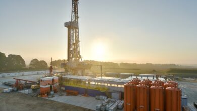
The closed-loop separation system (Figure 1) is based on water-injection methods to separate gas, liquids and solids in a closed tank. The separated return streams are individually handled so they can be disposed of in the most appropriate manner.
The compact system is made up of two skid-mounted units. One skid is the deluge pump, which provides water for the process. The pump recirculates water within the system to improve dust suppression by pre-wetting cuttings and solids surfaces in the flow line. The deluge pump is also used in conjunction with automated (PLC-controlled) level gauges to maintain constant liquid levels automatically.
The second skid contains a large tank and the remaining separation system components. Cuttings, gas and liquids from the rig enter the tank through a blooie line. Water is injected into the primary flow line, and an expandable inlet reduces the flow velocity rate of the incoming well returns.
A chain curtain in the tank knocks most of the solid particles to the bottom of the tank as they pass through the expandable inlet. Water droplet spray nozzles wets fine solids and allows gas to break away from the larger solids remaining in the mixture after it passes through the chain curtain.
The tank is built to contain a deflagration caused by a back flash flare when flaring gas. In addition to the chain curtain, the tanks have several other components: a plate-back separator splits oil and fine solids from water, which cleanses the water so that it can be recycling through the system; a mist pack prevents water from entering the flare line; and sensors in the tank monitor system fluid levels. A programmable logic controller monitoring the sensors automates the system’s fluid level management.
The flare line routes separated gas components to the company’s flaring equipment, which operates more effectively because solids content has been minimized. Separated liquids and solids pass through a slurry pump for transport to the rig’s solids control system, and an oil pump sends skimmed oil to a separate container (manual operation).
The system adheres to a number of design standards, including ASME Boiler and Pressure Vessel Code section VIII for the design and fabrication of pressure vessels, ASME B31.3 for process piping, the NFPA 69 standard on explosion prevention systems and NFPA 70 national electrical code.
The system has a borehole volume of 250 cu ft/hr and a slurry volume of 1,445 cu ft/hr (180 gal/min). It is capable of handling total gas returns of 6,000 standard cu ft/min and has an unload rate of 550 gal/min (785 bbl/hr) and surge capacity of 32 bbl.

Field trials
Initial operator testing of the Sentry closed-loop separation system was conducted on three wells in Fayette County, Penn. A total 21,486 ft were successfully air drilled, and the system performed as designed and met all set objectives.
The separator technology was designed to enhance safety, improve control reliability and the operator interface, slurry transport, makeup water quality, dust mitigation, instrument air quality and data collection.
Design parameters included the elimination of earthen pits. To do so, it was necessary that the system handle up to 6,000 standard cu ft/min produced gas and injected air plus 100 gal/min of injected and/or produced liquids, and 150 cu ft/hr of solids up to ¼ in.
The system had to separate gas from liquids and solids, and pump the slurry to the rig solids control system. It was also important that the system mitigate risks associated with air and gas returns to an acceptable level. The separator had to support continuous flaring during normal operations or cold venting when explosive mixtures were present. Dusting and mist drilling capabilities were also necessary.
All this had to fit in a package that met US road limits – 13 ft, 6 in high by 8 ft, 6 in wide, and 80,000 lb total trailer weight.
Well applications
Performance indicators were developed for the three wells. On Well 1, the indicators were to test and operate the tank to ensure fluid level automation functioned as planned, to ship solids up to stated performance limits, and verify the proper operation of the flare shutdown system on loss of positive pressure or methane readings within explosive limits.
Well 1 drilling operations also sought to maintain normal operating levels and achieve minimal dust/liquid carry over to the flare. A post-well inspection was conducted to observe the tank’s condition and look for possible improvements.
In drilling Well 2, the same indicators were applied while reducing the manual operations for shipping solids. Dust suppression and elimination of liquid carry over to the flare were also implemented. Well 3 was drilled with the same KPI.
Well 1 was drilled in four sections – 20-in. hole to 325 ft; 15-in. hole to 530 ft; 10 7/8-in. hole to 2,275 ft, and 7 7/8-in. hole to 6,800 ft. The operation met all KPI objectives, and the closed-loop separation system operated as designed. Lessons learned led to minor adjustments to improve performance, including changes involving sensor meters, flow level control, the flare stack igniter and flare stack dust suppression.
Lessons learned also identified sources of foam injection inconsistencies and the effects of the rig system’s air feed temperature and wetness. The need for good communications with the rig was also noted, as slow drilling rates reduced cuttings production and falsely suggested separator problems.
The second well had the same plan and was drilled to 6,800 ft. Not all KPIs were met, and the system faced different challenges compared with the first well, including a 15-gal spill from carry-over to the flare stack. Slurry pumps were also plugged due to very large returns from a mine. As a result, the separation system was bypassed in the 15-in. hole section. Additional adjustments were made to the system in preparation for the third well.
The same casing plan was applied to Well 3, and it was drilled to 8,266 ft. Similar challenges to Well 2 were experienced, but the well was drilled according to plan with the separation system operating as designed.
Overall the system operated as designed and met all KPIs. Challenges to the operation were minor and resolved through design and procedural adjustments.

New solutions
A changing regulatory climate requires a new look at old procedures. Increasingly, traditional methods of air drilling are recognized as sources of safety and environmental problems. Compliance requires new separation technology to minimize the environmental impact of air drilling and improve safety. Fields tests have shown that this level of compliance is achievable with an innovative approach to eliminating open pits and enhancing dust suppression.