Closed-loop drilling optimization system: implementation and field results from large-scale deployment
Parameter limit roadmaps played key role in ROP/MSE optimization, while automated protocols allowed for mitigation of drilling dysfunctions
By Stephen Lai, Lars Olesen, James Ng, Aaron Eddy, Sergey Khromov, Dan Paslawski and Ryan van Beurden, Pason Systems; Gregory S. Payette, Benjamin J. Spivey, ExxonMobil Upstream Research Company

The goal of practical automation is to perform repetitive, precise and rule-based tasks. Rotary drilling performance can be maximized by continuous adjustment of WOB and RPM in response to changes in ROP and mechanical specific energy (MSE) while detecting and mitigating dysfunction.
This workflow is a prime candidate for automation; however, developing the technology for wide-scale use presents technical and human-factor challenges. This article describes learnings from a control and optimization system that was deployed on over 270 rigs and 1,700 wells in eight countries in 2018 and 2019.
ROP improvements of 7.2% and 8.0% (two-year average) and 9.7% and 17.3% (last year average) were observed in the vertical and lateral sections, respectively.
Most of the deployments have been located in North America, and the system has been used by over 50 rig contractors and 170 operating companies. To the authors’ knowledge, it is the most widely deployed system of its kind.
Control and Optimization
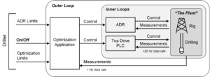
The optimization application, autodriller (ADR) and top drive PLC are arranged in a nested control loop. The optimization system is the outer supervisory loop, which interacts with the autodriller, top drive PLC and rig sensors at a 1 Hz rate. The ADR and top drive PLC are inner loops that control the drilling process at a much faster rate.
The driller does not directly control the autodriller and top drive setpoints as in traditional open-loop systems. Instead, the driller’s main responsibilities are to set appropriate parameter limits for both the optimization application and autodriller sub-system.
ROP/MSE Optimization
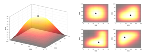
The objective is to find settings for WOB and RPM that maximize ROP. This optimization problem can be visualized as a search for the “top of the hill” when ROP is mapped as a function of WOB and RPM as in the left side of Figure 3. MSE is a performance measurement parameter that quantifies the amount of energy used to remove a unit volume of rock. It is calculated using common surface parameters, such as WOB, torque, RPM and ROP, and provides an indication of the bit’s drilling efficiency in real time. In cases where a balance between high ROP and low MSE is desired, an objective function containing a prescribed weighting for both ROP and MSE can be used in place of ROP as the main optimization goal.
Technical challenges in designing and deploying online drilling optimization systems at scale include geologic diversity, formation heterogeneity and non-standardized drilling rigs and equipment. In most land-based wells, formation characteristics can change rapidly over both short and long depth intervals.
A strong indication of this is the significant variation observed in measured drilling parameters when constant ADR setpoints are used. In the context of the ROP optimization problem depicted in the left side of Figure 3, the surface represents only a snapshot at a specific depth, which changes in shape and magnitude during the course of drilling. That is, the ROP achieved for a set of WOB and RPM values does not remain static throughout a given depth interval.
Similarly, the optimal combination WOB and RPM may also change throughout the course of drilling as in the right side of Figure 3. The changes that occur are not known in advance, but the system should ideally continue to operate at the optimal point. A pragmatic approach to this type of problem is to continuously search for the “top of the hill.”
The system implements a method for real-time, non-model-based optimization known as extremum seeking control (ESC). This class of optimization routine employs continuous fluctuation signal inputs to the system to adaptively search for an objective.
A key change in the drilling process is to build and follow a parameter limit roadmap, defined as the min/max engineering limits for parameters over specific depths. This is vital to allow the ROP/MSE optimization algorithm to search a two-dimensional space defined by WOB and RPM limits. Contrast this with the historical practice of drilling to a WOB setpoint often resulting in long periods of time/depth drilled at the same setpoint; a “set it and forget it” approach.
The depth interval boundaries normally coincide with known formation tops or locations where the rig plans to run casing or perform a trip. Parameter roadmaps should include WOB, RPM, differential pressure, torque and SPP in accordance with equipment or engineering tolerances. The roadmap may contain some depth intervals where the optimization system is not enabled. Usually, these intervals correspond to abrasive or non-homogeneous formations where ROP-limited “control drilling” is necessary to prevent bit damage.
Once a parameter limit roadmap has been created, it should be followed during drilling of the well. Minor modifications to specific depth values may be necessary, but, in general, the optimization application and ADR should be set to the limits written in the plan.
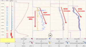
Figure 4 shows a field-based example of optimization using ESC, where a sinusoidal fluctuation (wave) is imposed on both the WOB and RPM setpoint signals. The WOB and RPM achieved by the ADR and top drive, respectively, track closely with the wave setpoints. During drilling of the stand, the ESC algorithm has determined that increasing the WOB and RPM is best for optimization. This is confirmed with a corresponding increase in ROP and constant trend in MSE. The sinusoidal patterns in WOB and RPM are readily visible to the driller and provide an indication that the algorithm is continually searching for the optimal point.
Dysfunction Mitigation
The mitigation of drilling dysfunctions is treated as a separate task from ROP/MSE optimization. When dysfunction is detected, ROP/MSE optimization is paused, and an automated protocol is executed to remove the dysfunction condition. There is a growing list of known drilling dysfunctions that occur often and benefit from automated mitigation protocols: stick-slip, formation stringers, motor stalling and lateral vibration.
The application software has been architected in such a way that integration of new protocols can be done with minimal design effort. Current research is focused on expanding the list of protocols.
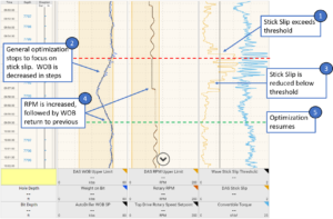
Figure 5 illustrates how stick-slip is mitigated by executing a software protocol when the severity estimate exceeds a preset threshold. The protocol logic follows an industry-standard practice for alleviating this type of dysfunction and mimics what a driller would normally do in such a situation.
ADR Management
The optimization algorithm requires precise control of WOB and for the autodriller to be operating in a stable state. In a typical ADR, the driller can provide simultaneous setpoints/limits for four parameters: WOB, ROP, DP and torque.
Undesirable conditions can occur in autodrillers, such as instability in control loop behavior when multiple parameters are close to their limit. The system automatically detects this and numerous other undesirable conditions, and a software protocol is executed to return the ADR to a satisfactory state.
Human Factors
The human element is always one of the largest challenges when introducing new automation technology. Three specific challenges were encountered repeatedly with different operators, contractors and rig crews:
- The need for full buy-in from the operator and across its multiple sub-contractors;
- The need for user trust in the system; and
- User perception of system performance in highly variable formations.
The main finding from the user experience design of this system was that its success was strongly dependent on the level of trust from the user.
This manifested in the deployment phase of this project, where it was observed that results improved significantly when a high-quality roadmap was created before drilling began and the plan was followed (trusted) during drilling operations.
Case Study
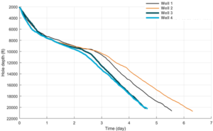
Figure 6 illustrates a typical case of performance improvement on several offset wells from the same drilling pad, showing the depth versus time for periods of on-bottom drilling. Wells 1 to 4 were drilled in sequential order in the Bakken. Wells 1 and 2 were drilled without the system, and Wells 3 and 4 were drilled with the system.
Several drilling performance metrics were calculated for each well. The rotary ROP improvement was 19.7%, 21.9% and 36.7% for vertical, build and lateral sections, respectively, when the system was used. On average, the total number of stationary times was reduced from six to four, and the number of unplanned stationary times (i.e., NPT) was reduced from three to one. Finally, the average spud-to-TD was lowered from 18.8 days to 13.25 days, which represents a 29.5% reduction of total drilling time. DC


