UBD unlocks pay in North Sea wells
Closed-loop circulating system, disc-stack centrifuge, downhole isolation valve among key project components
By Geoff Gough, Steven Talbot & Hasse Moos, DONG Energy
This article reviews an offshore underbalanced drilling project in the Danish sector of the North Sea undertaken during summer 2010. Two oil wells were drilled from a jackup, with produced oil and gas transferred to the accompanying production platform. A closed-loop circulating system was employed to mitigate the potential for release of gas vapors, completely bypassing the rig’s pits and shakers. Crude oil was initially selected as the drilling fluid for the reservoir section to reduce the baseline coefficient of friction and minimize the potential for emulsions. A bespoke disc-stack centrifuge was used to control the composition of drilling fluid injected into the standpipe by removing fine chalk solids and separating the oil from any produced water.
Underbalanced drilling (UBD) was successfully implemented on this two-well campaign. No appreciable losses were encountered during the drilling of the wells.
The horizontal 6-in. reservoir sections were drilled underbalanced to reach reserves targets and verify underbalanced drilling as a viable technology for unlocking previously unrecoverable reserves in the north of the field.
This situation arose due to the variations in pore pressure and fracture gradient observed along a typical horizontal wellbore in a low-permeability matrix. It is not unusual for the pore pressure in one part of the horizontal section to exceed the fracture gradient at another, meaning that an overbalance fluid column cannot be supported by the rock strength of the weakest zone.
The operating philosophy for this implementation was to keep the bottomhole pressure sufficiently low to minimize losses in the lower-pressured hole sections while being set up to allow for hydrocarbon production when drilling the overpressured sections. Stimulation is seen as a requirement in the field for enhanced reservoir contact beyond the wellbore to ensure capture of reserves; thus, the avoidance of formation dam age and improved productivity, although beneficial, were not drivers for UBD in this case.
The two wells in this campaign were flank wells. The initial well primarily targeted a higher-pressure formation and was, as a consequence, underbalanced through most of the lateral. The second well targeted a lower-pressure zone to appraise its upside potential and was overbalanced near the heel and underbalanced at the toe, especially as the higher-pressure zone was entered.
The field’s native produced crude oil was selected as the primary circulating medium to minimize the amount of phase separation required and to simplify the circulating system. It was anticipated that the crude oil would serve to reduce friction and, as a result, the amount of lubricants and chemicals required to maintain the drilling fluid system. However, the crude oil was found to have a detrimental effect on the bottomhole assemblies (BHAs) and may have led to increased wear on the rubber BOP elements. Subsequently, SRP water (sulfate reduced platform water) was used as the drilling fluid.
The equipment selected and concepts chosen are believed to be without precedent in the drilling of oil wells in the North Sea.
UBD Equipment Selection
The UBD equipment used allowed hydrocarbons to be produced at surface while drilling. The system was designed to separate the produced hydrocarbons from the active circulation fluid and drilled cuttings. Separated hydrocarbons were routed back to the production platform’s processing facilities while the cuttings were reinjected into an existing wellbore.
The underbalanced drilling equipment included a purpose-built, closed-loop surface handling system sized for maximum inflow of wellbore fluids and safe transfer of hydrocarbon liquid and gas to the production platform, fully bypassing the rig’s pits and shakers. Figure 1 provides an indicative process flow diagram of the final surface system configuration.
To facilitate pumping of produced crude oil as the drilling fluid with the rig’s pumps, it was necessary to reclassify the mud pump room as a hazardous area. Specially constructed enclosures surrounded the pumps, the ventilation system was reconfigured and several electrical devices were replaced.
A previous drilling campaign demonstrated that the surface system employed there was unable to effectively separate oil and water in the presence of the fine chalk cuttings. The typical size of the solids was less than 50 microns, and the rig’s fine shaker screens were ineffective. The inability to remove the fine solids from the circulating system led to increased concentrations in the well effluent and, in combination with friction-reducing lubricants, formed emulsions that could not be broken down at the surface separation package. As a consequence, a high-speed disc-stack centrifuge was selected as a way of removing the fine drilled solids and providing additional oil-water separation.
The disc-stack centrifuge was specifically adapted for this underbalanced drilling campaign, and it is thought to be the first deployment on such a project. Disc-stack centrifuges are used in the offshore oil and gas industry for produced water cleanup. It consists of a frame, drive motor, transmission and the main separator bowl. The motor is vertically mounted on the lower frame. The bowl spindle is mounted in a spindle unit opposite the motor. A drive belt transfers the power between motor and bowl spindle. The separator bowl is mounted on top of the vertical spindle and rotates at high speed inside the bowl casing.

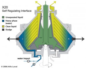
The bowl is of the continuous solids discharging type, with outlet nozzles fitted at the bowl periphery (Figure 2). The separation process occurs inside the rotating bowl at g-forces in excess of 5,000; annular channels, between the stacked discs, can be regarded as a series of parallel separation vessels.
The machine is fitted with the “optiphaser,” which automatically keeps the interface in the correct position, ensuring optimal separation while preventing hydrocarbons from entering the solids and water outlets, even in the case of 100% oil in the feed. The disc stack is fully inerted and suited for ATEX hazardous area zone 1 and potentially flammable feed. The oil flows against the upper side of each disc toward the center of the bowl and exits through a “paring disc” into the outlet pipe. Water and solids flow outward against the underside of each disc toward the periphery of the bowl.
The slurrified solids stream is discharged continuously toward a screen inside the frame hood, then discharged through the solids outlet nozzles and subsequently routed toward the cuttings reinjection unit. The water is also discharged via a “paring disc” and routed back into the circulating system.
The disc-stack centrifuge was designed to tolerate up to 6% solids in the feed stream. A high-pressure hydrocyclone was used for coarse solids removal (greater than 100 microns) and was situated directly downstream of the high-pressure separator to facilitate real-time sample catching. The solids underflow was routed to twin sample catchers integral to the separation package. The actual samples were passed to the offshore geologists for evaluation. In addition, a more conventional decanter centrifuge was supplied, offering a degree of redundancy.
A downhole isolation valve (DIV) and backup snubbing equipment were incorporated to ensure positive pipe control at all times and to improve tripping rates. The DIV is viewed as a critical component from both a well control and efficiency perspective. The conventional BOP stack was modified to facilitate the inclusion of a 10k snubbing stack. To aid snubbing operations, an operational blind ram was included with only a pipe ram below to provide a longer lubricator section when running the BHA.
In addition to this operational blind ram, a conventional stack-up containing variable bore rams, blind-shear rams, 4-in. pipe rams and an annular preventer, capable of holding 10k pressure above and below, were installed. A flow spool was placed above the rig annular, in preference to a conventional bell nipple assembly, diverting flow to the primary flow line. The snubbing BOPs were installed above this flow spool, and the rotating diverter was installed between the snubbing BOPs, the snubbing slip cage assembly and a floor-mounted snubbing jack.

A rotating control device (RCD) was installed at the top of the pressure-control equipment, maximizing the stripping area. Figure 3 shows a stack-up drawing for the 6-in. UBD section. There was a specification break at the 5k-rated rotating diverter and downstream of the emergency shutdown (ESD) valve and 10k operational valve on the primary flow line.
The RCD, drillstring non-return valves and dedicated UBD choke manifold were primary well control barriers completely independent of the drilling BOPs.
A purpose-built, two-stage pressurized separation system was installed to remove produced gas from the returned well effluent. The primary separation vessel was specified to allow gas transfer to the production platform’s separation train at its operating pressure, approximately 27 barg (gauge). The primary separator was vertical, optimizing surge protection while maintaining a high gas capacity. The second-stage separator was configured to operate at low pressure, ensuring that optimal volumes of gas were evolved and routed to a low-pressure flare, thus reducing gas breakout in the downstream atmospheric circulation system.
A horizontal second-stage vessel was selected to improve separation and foam handling. In a horizontal vessel, the drops or bubbles do not have to settle or rise through a countercurrent flow, and the increased surface area afforded allows more bubbles to escape. One downside of a horizontal vessel is the large footprint required. To partially compensate for this, other modular equipment items were placed on an additional level above the horizontal vessel.
In addition, the pressurized separation system was specified to include liquid-level monitoring with modulating control valves to improve metering accuracy, in-line y-strainers to protect the level-control valves, high and low liquid-level and pressure alarms, along with a manifolded pressure relief system and lines. Each pressurized vessel contains dual relief valves sized, in combination, according to the maximum flow rate through the vessels.
Natural gas injection points were required on both vessels to facilitate pressure testing and start-up. The gas was supplied direct from the adjacent production platform. To prevent any iron filings from blocking magnetic level-control systems and damaging downstream pumping systems, in-line magnet traps were employed. The surface system was configured to automatically shut down on high-pressure, high-level power failure and pneumatic instrument air failure. Five manually operated ESD panels were located across the drilling rig, with an additional manual shut-down panel situated in the production platform’s central control room. Enhanced fire and gas safety systems were required to cover the surface inventory of flammable fluids.
The data acquisition system was specified as a central data hub to assimilate the data from not only the UBD equipment modules but also mud logging and drilling data. The user-configurable system could upload data to the intranet/internet for remote viewing. It also supported the WITS protocol, with fluid flow rates and operating pressures monitored on trend screens at the separation package, the drill floor, the supervisor’s office and the production platform.
The closed-loop atmospheric circulating system was designed to safely contain hydrocarbons returned from the wells while drilling and tripping. The selected system incorporates five tanks, each approximately 30 cubic meters. These effectively replaced the rig’s pit and shaker systems. In addition, the closed-loop system was designed to export clean oil to the production platform’s processing facilities, maximize degassing of returned fluid and provide feed water to the disc-stack centrifuge and hydrocyclone (Figure 1).
The circulating fluid, including the fine drill cuttings and produced oil, is exported into the feed tank from the pressurized separation package. A vacuum degasser is placed on the feed tank to minimize entrained gas breakout within the circulating system and prevent solids deposition by keeping the fluid agitated.
From the feed tank, the fluid is pumped to the decanter centrifuge, where solids as small as approximately 40 microns are removed and sent to the cuttings reinjection unit. The fluid is routed to the active tank, then pumped to the disc-stack centrifuge, where the fluid is separated into three phases – oil, water and solids.
The solids stream is sent to the cuttings reinjection unit, the water is returned to the circulating tank and on to the drilling pumps, and the incremental produced oil is routed to the export tanks and on to the triplex oil export pump. The diesel-powered triplex pump transfers the produced oil to the production platform at approximately 27 barg.
UBD Drilling Fluid Selection
Base oil was initially selected as the drilling fluid; however, as inflow was received from the well, the base oil was expected to be diluted and eventually replaced by produced crude oil. Oil was expected to lower the friction factor and therefore generate smoother drilling conditions. This was expected to enable sliding with motors for longer periods of time and to decrease the risk of BHA and drill pipe failures due to reduced stick-slip.
On a previous campaign, BHA failures were attributed to high levels of vibration and shock loading, in part caused by high friction factors when drilling with SRP water. Consequently, oil was selected to drill the UBD reservoir sections. A SRP water contingency was available.
After multiple BHA failures on the first well, it was decided to change to the alternative SRP water. This was successful, with the surface processing system delivering four-phase separation. The disc-stack centrifuge and selected demulsifier were the key enhancements compared with the previous campaign. The recorded drilling parameters clearly demonstrated that SRP water, with friction-reducing lubricants, generated significantly lower friction factors than the crude oil, with BHA reliability.
It has been concluded that future underbalanced drilling in the field should be conducted using SRP water with the lubricant and demulsifier combination that was successfully employed.
A benefit of using SRP water is the provision of a higher hydrostatic head than can be obtained with crude oil, thereby reducing the surface pressure applied to the rotating head when maintaining a higher bottomhole pressure. In addition, by removing oil from the circulating fluid, the risks associated with spills, releases, etc, are significantly reduced.
System Strengths
The closed-loop surface separation system recovered oil and gas to the production platform. Continuous solids removal from the circulating and fluid export systems demonstrated the effectiveness of the process selected.
A detailed onshore commissioning program was undertaken on the various equipment modules. The testing involved oil, water, solids, lubricants, demulsifiers and nitrogen. Modifications were implemented after troubleshooting was performed. The onshore commissioning of the surface separation and circulating system was shown to significantly reduce offshore nonproductive time (NPT) and provide effective training for personnel.

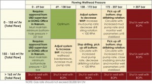
The wellhead parameters were successfully maintained within the planned matrix (Figure 4). Bottomhole pressure could be controlled as desired to optimize inflow within a prescribed range to maintain borehole stability and minimize the potential for hydraulic fracturing. Data gained while drilling and during flow tests enhanced reservoir knowledge and confirmed the position of faults. Effective hole-cleaning was maintained during the drilling of the 6-in. horizontal reservoir section.
The in-line sample catchers deployed downstream of the hydrocyclone were effective and easy to operate. Real-time sampling was upheld throughout drilling of the reservoir sections. Significant volumes of metallic filings were removed from the circulating system, with in-line magnet traps preventing damage to the process equipment.
The pre-campaign laboratory chemical test program proved beneficial. The addition of friction-reducing lubricants reduced bottomhole torque and drag. Lubricant was continuously added at a rate of 50-75 liters/hr, and the initial circulating system was “pre-dosed” with 1% lubricant prior to drilling the shoe. The bespoke demulsifier proved effective even in the presence of lubricant when continuous dosing was necessitated.
The surface separation package and tank farm relied on pneumatic controls as opposed to a PLC-based system, simplifying equipment commissioning and troubleshooting and eliminated the requirement for a dedicated software engineer onboard.
System Weaknesses
The high-speed, disc-stack centrifuge was initially plagued by shutdowns due to plugged nozzles and high vibrations. This was rectified by adding in-line strainers in close proximity to the inlet and operating the backup decanter centrifuge, in series, upstream of the disc stack (Figure 1).
Liquid carry-over from the high-pressure separator at low gas rates was observed throughout the campaign. The liquid carry-over affected metering accuracy and the material balance, in addition to a real-time reservoir characterization project that was implemented on the first well. The carry-over is considered to be a result of the vessel’s cyclonic internals proving ineffective at low turndown; a redesign will be required for any future campaigns.
Liquid metering, especially coriolis meter performance, was intermittent. At this stage, the reasons for the poor metering performance are inconclusive. It is postulated that one or a combination of causes – vibrations, entrained gas, solids content and crude oil composition – were significant factors. Further analysis is ongoing.

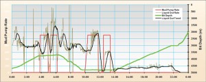
The main liquid flow meter was located downstream of the low-pressure separator’s level-control valve and consequently was subject to intermittent flow, as illustrated in the daily plot in Figure 5. The meter location and the level-control valve action have been highlighted for review prior to future deployment.
The data acquisition system QA/QC requires optimization at the interfaces, i.e., other service companies and the production platform. In the future, it is recommended that the full system is tested during onshore commissioning. Where this is not possible, significant time should be allowed to validate the system offshore prior to the commencement of UBD operations.
Downhole Isolation Valve (DIV)
It is recognized that the DIV is an important component for UBD operations, from both a well control and efficiency perspective. The DIV is used to isolate the reservoir from the surface well control equipment when the bit is above the DIV, thus allowing the trip to be conducted conventionally, without having to rely on stripping and snubbing, as well as supplying an additional barrier to flow. Tripping out of the hole conventionally is significantly quicker than stripping and snubbing, providing a means to reduce operational time significantly.
It is evident that the DIV was a significant component in the successful delivery of these UBD wells. Unfortunately, during both this campaign and previously, DIV reliability was an issue. The design of the tieback string hanger meant that every time the tieback string was run, the well had to be suspended and the BOP stack nippled down in order to allow the DIV control lines to be terminated. This was time-consuming and should be avoided in the future by designing a dedicated wellhead spool for the tieback hanger, with control line ports or galleries.
Given the importance of the component, an evaluation to increase the number of DIVs from one to two will be conducted, addressing the incremental time associated with drilling large hole sizes and running larger casing strings, as well as potential UBD tripping time savings.
The snubbing unit wasn’t used, for the most part, and consideration will be given to its future deployment. The unit increases the well control rig-up time and adds to the stack-up height requirement. Given that an additional wellhead spool has been recognized as beneficial, consideration will also be given to reducing the inventory of equipment in the well control stack.
The reason for this recommendation is that having two DIVs would significantly reduce the likelihood of DIV failure; therefore, the probability of having to strip and snub all the way to surface is also reduced. In the event that both DIVs were to fail, then a temporary floor-mounted snubbing system could be considered as a contingency.
Well Performance
The first well was underbalanced throughout and produced oil with associated gas and no formation water, while drilling. Underbalanced conditions were achieved with both crude oil and SRP water as the drilling fluid. The productivity was at the higher range of what was projected, and the production observed represents the high influx case.
There was no production seen while drilling the second well in the lower-pressure section even though, based on buildup measurements and the bottomhole circulating pressure, the well was underbalanced by 25-30 bar toward the end of the section. As expected, the low-pressure section was tighter, and it appears that an increased drawdown would have been required to produce. The toe was in the high-pressure section, and production was expected; however, no production was recorded while drilling. For underbalanced conditions to be maintained in this section, gas injection would have been required. It was felt that gas injection would add complexity to the operation and, with the benefit of hindsight, hole-enlargement issues may have been accentuated by the higher drawdown.
QHSE
Given the significant hydrocarbon inventory required for underbalanced operations and the number of operating personnel who were new to underbalanced operations, QHSE was a major area of focus. Zero lost-time injuries were recorded during the drilling campaign. Extensive planning was undertaken over the previous year to ensure that all hazards were identified and controls were put in place to minimize risks. Lessons learned from other UBD operations and the previous underbalanced drilling campaign were implemented to optimize operations. HAZOP, HAZID, pre-spud sessions, peer reviews and specific risk assessments were conducted to identify and mitigate risk. A risk register was established to manage, highlight and rank the numerous risks associated with the specialized operation.
A piping and instrumentation diagram was a controlled document, and any deviations were subject to a management-of-change process. The UBD operation was conducted under a permit-to-work system. All personnel were required to take part in a specially constructed induction program prior to working offshore. A third-party performance improvement company was contracted to provide offshore QHSE personnel. Their role was to ensure that all toolbox talks, JSAs, risk assessments, etc, were attended, properly managed and enforced. In addition, they facilitated the implementation of safety programs by involving themselves with the workforce. This was extremely successful in gaining the drilling contractor personnel’s respect and participation in safety programs.
Conclusions
The offshore underbalanced drilling program with a closed-loop separation system was successful and, as a result, a further underbalanced drilling campaign has been sanctioned. Drilling the UBD reservoir sections with crude oil was problematic. However, when the contingency SRP water and lubricants drilling fluid were introduced, drilling performance improved significantly.
This article is based on IADC/SPE 143096 at the IADC/SPE Managed Pressure Drilling & Underbalanced Operations Conference & Exhibition, 5-6 April 2011, Denver, Colo.
References
- Gough G. and Graham R.: “Offshore Underbalanced Drilling – the Challenge at Surface” paper IADC/SPE 112779 presented at the 2008 IADC/SPE Drilling Conference held in Orlando, Florida, U.S.A., 4–6 March 2008
- Arnold K.E.: PETROLEUM ENGINEERING HANDBOOK, Volume III, FACILITIES and CONSTRUCTION ENGINEERING,
Chapter 2 – Oil and Gas Separators, SPE 2006. - Arnold K.E.: PETROLEUM ENGINEERING HANDBOOK, Volume III, FACILITIES and CONSTRUCTION ENGINEERING,
Chapter 4 – Water-Treating Facilities in Oil and Gas Operations, SPE 2006. - Chirinos W.A. et al: “Liquid Carry-over in Gas-Liquid Cylindrical Cyclone Compact Separators” paper SPE 56582 presented at the 1999 SPE Annual Technical Conference held in Houston, Texas, 3-6 October 1999


