BP case study: MPD application supports HPHT exploration
BP transfers lessons from jackups to deepwater operation using semisubmersible
By Tom Scoular, BP Global Wells Organization; Kevin Hathaway, Wael Essam, Karlin Costa, Scott Johnson, Andy Rawcliff and Andrew Phillips, BP; David Burton, consultant
Following successful implementation of managed pressure drilling (MPD) in high-pressure, high-temperature (HPHT) wells drilled from jackups in the Eastern Mediterranean, BP Egypt in 2009 embarked on a plan to incorporate MPD into the drilling of a deepwater exploration HPHT well in the West Nile Delta using a semisubmersible rig. The MPD techniques and experience developed on jackup HPHT drilling operations were successfully transferred across to the floating rig operation.
This article will discuss the rig modifications required to install the MPD equipment on the semi, including installation of the rotating head in the marine riser. It will also review the operations carried out utilizing MPD techniques and give examples of how the equipment was used in the drilling of the last three hole sections. Some key areas considered essential to the success of this technology on a floating rig in a demanding HPHT environment and the benefits associated with the MPD operation will be highlighted.
Introduction
BP Egypt drilled its first HPHT well in the Nile Delta in 2003. Following this success, it has continued HPHT exploration and appraisal drilling in the area, covering both the shallower water of the East Nile Delta, where a jackup with 15,000-psi well control equipment was used, and the deeper water of the West Nile Delta, where semisubmersibles are required.
The deeper formations of the Nile Delta exhibit all the classic characteristics of HPHT drilling environment. Pore pressure-fracture gradient (PP-FG) window is typically less than 0.3 ppg equivalent mud weight (EMW) in the deep reservoir sections, and dealing with losses and gains has historically been a significant source of nonproductive time (NPT). In several cases, such NPT has led to a cessation of exploration wells drilled in the Delta prior to reaching target depth.
Further, the Nile Delta exhibits significant pore-pressure ramps and regressions. This, combined with a complex geological basin for pore pressure prediction, can result in a challenging downhole environment.
In 2007, BP used a rotating head and a simple manual choke on a jackup with 15,000-psi BOP to drill a deep HPHT exploration well. This enabled constant bottomhole pressure (BHP) control to be achieved and was considered successful. This well is believed to have been the deepest well drilled in the Mediterranean at the time, encountering pressures and temperatures in the upper range of the conventional HPHT envelope.
The use of MPD on this well and three subsequent HPHT wells drilled from the same jackup was successful. The drilling team steadily increased its understanding of the various techniques available and built up experience with the system.
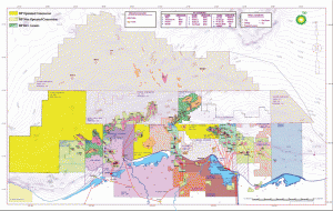
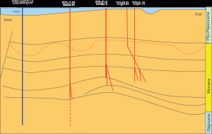
In 2009, planning started on a deepwater exploration HPHT well called WMDW-7, located in the West Nile Delta, approximately 110 km offshore from Alexandria (Figure 2). The well was planned to penetrate the deeper Oligocene formations in the West Nile Delta for the first time, going approximately 1,200 meters deeper than any other wells previously drilled by BP (Figure 3). Based on the success achieved in the shallower-water exploration program, it was decided that MPD would be a key enabler in order to meet the objectives of WMDW-7. The team started to investigate the most suitable way of installing a rotating head on the semi with 15,000-psi BOP that would drill the well.
WMDW-7 was spud in 2010 in 1,107-meter water depth. To the best of the authors’ knowledge, this was among the deepest-water applications of MPD from a semisubmersible at the time. BHP and temperature were predicted to be 17,000 psi and 170°C, respectively. The well reached its target objectives in March 2011. MPD was employed once the 13 5/8-in. casing was run and used continuously to drill 2,500 meters beyond this point to final well TD at 6,350 meters.
MPD in Nile Delta
The successful implementation of MPD in the HPHT jackup wells in the eastern side of the Mediterranean had established a track record for the technology that was to be transferred to the deepwater region to drill the first Oligocene penetration there, the WMDW-7 well.
This implementation of MPD is based on the concept of applying a surface pressure to the well using a pressurized closed-loop circulation system. The system consists of a rotating control device (RCD) mounted on the riser above the BOP, and in which a bearing assembly is housed during the critical hole sections, sealing the well around the drill pipe and directing the return flow from the well sideways across the RCD to a dedicated flow line. The flow then goes through a dedicated MPD choke manifold, where chokes are manipulated to apply the desired amount of surface backpressure (SBP) to the well, precisely controlling the BHP.
In periods of no flow or low flow, with the downhole pumps off, the loss of the effect of annular friction losses (AFL) on BHP is compensated for by either shutting the well in on the chokes or by using an auxiliary pump and a secondary surface flow system to generate flow across the chokes and create the desired backpressure.
Four HPHT wells were drilled with MPD using a 15,000-psi jackup rig in the Eastern Mediterranean. The constant BHP technique was specifically adapted to the drilling of exploration wells to:
• Enable use of connections and pump-off events to get a gas signature – a very useful pore-pressure detection method;
• Enhance well control awareness and flow-checking procedures; and
• Optimize tripping procedures.
Implementation on semi
Implementation of MPD on the semi created several challenges that needed to be addressed; these resulted from the floating drilling configuration, with the BOP on the seabed and a heave-compensated riser connecting the rig to the BOP through the water column.
Incorporating the RCD into the riser string
The RCD had to be installed in the riser string above the water line and needed to be in the fixed part of the riser; hence, the riser telescoping joint (TJ) would have to be above it. The spaceout was carefully considered in light of the rig’s operating air gap, rig motion characteristics and required heave compensation, required crossovers to connect the RCD to the riser components, and running considerations. The available space meant that the rig’s original TJ was not usable. Therefore, another smaller “mini” telescoping joint needed to be built, in addition to the RCD crossovers. All new components had to have the necessary tensile rating to run the riser and BOP and sufficient inner diameters to run all downhole tools, such as wellhead wear sleeves, BOP test plugs and the RCD bearing itself.
Maintaining suitable heave compensation for the rig
The rig motion characteristics and heave history in the region were reviewed to identify the required heave compensation above the RCD. This was then translated into the specification for the mini-TJ required stroke length.
Using the marine riser as a pressure containment vessel
The location of the pressurized closed-loop circulation system at the top of the riser meant that the marine riser would become part of the pressure containment system. The pressure ratings for every component of the marine riser string were studied and operating limits were identified in terms of maximum allowable mud weight versus maximum allowable surface pressure, and tensioner system capability. The operating limits were then used to define the operation of a pressure relief line in the MPD surface system that would protect the riser in case of overpressure.
Surface System layout
The placement of the MPD system components and the routing of the flow lines between the various system components was designed around the layout of the rig to optimize the working environment of the MPD operators, to apply minimum hydrostatic backpressure on the well due to vertical drilling fluid flow, and to minimize the impact that the MPD system would have on the operation of other aspects of the rig. A HAZOP of the system was carried out with a multidisciplinary team as part of the planning process before finalizing the layout of surface lines and equipment.
The interface points between the MPD system and the rig circulation system were chosen to minimize any additional hydrostatic head on the well. Control panels of the various system components were strategically placed in proximity to the worker stations, particularly for frequently accessed or critical controls. The system layout was reviewed and modified where necessary to avoid introducing new hazardous conditions, such as low overheads, trip hazards, impeding access to life-saving equipment or escape routes.
Walkways were built above certain parts of the system, and stairs and handrails were added to increase worker safety.
Marine Riser, Mini-TJ
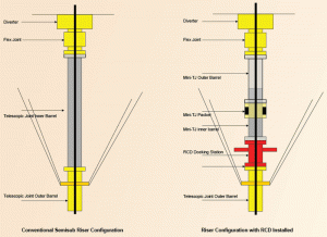
Riser Configuration with RCD and mini-TJ
The riser string needed minor modifications to incorporate the RCD and mini-TJ. The diverter adaptor, going from the 21 ¼-in. API flange on the bottom of the diverter to the rig’s riser connector, was removed from the stackup to maximize space available to the mini-TJ and hence its stroke length.
One challenge encountered was that the tensioner ring, where the marine riser tensioner connects to the fixed part of the riser string in normal operating conditions, was part of the rig’s TJ. The rig’s TJ was no longer required for heave compensation due to the spaceout considerations, but nonetheless it was required for the connection to the tensioner system. The solution proposed was to keep the rig’s TJ in the riser string but remove the locking system, packer housing and inner barrel.
The remaining joint would have the tensioner ring on it, and the RCD would be installed at its top. To connect the RCD to the outer barrel, a special crossover was built, and a 2,000-psi flat washer-type elastomer seal was designed to be installed in this particular connection to maintain pressure integrity below the RCD. The mini-TJ was to be installed directly above the RCD, with the top of the inner barrel mating with the bottom of the rig’s diverter (Figure 1).
Design and Fabrication
A mini-TJ was designed and built for the well. A statement of requirements (SOR) was prepared for the mini-TJ identifying its specifications in line with the operating requirements. A minimum stroke length was identified based on available space and historical heave data. Top and bottom connections were specified to match the upper flex joint and the top flange of the RCD, taking into consideration the tensile ratings required.
The tensile rating for the mini-TJ and all ancillary components was established based on the expected weight of the BOP and riser in this water depth with a suitable safety factor, for both the extended and collapsed positions of the TJ. The tensile rating drove the specification of the TJ body material, the specification of the welds and fasteners, and the design of the locking system. A manual (pin) locking system was chosen to maximize the mini-TJ’s available stroke. The inner diameter was chosen to allow the running of all anticipated large-diameter downhole tools up to the 19.6-in. RCD bearing. A compact dual packer housing to seal the space between the inner and outer barrels was designed to maintain the required seal while minimizing impact on the available stroke length.
Compliance with the relevant API Specification 16F (Marine Drilling Riser Equipment) and Recommended Practice 16Q (Design, Selection, Operation and Maintenance of Marine Drilling Riser Systems) was required for all aspects of the design and manufacturing process, including an extensive factory acceptance testing program that was undertaken at the manufacturer’s facility with a specially built test unit.
Rig deployment, Training
Several onshore and offshore training sessions were held with key project personnel, including offshore drilling contractor personnel and service company crews, to familiarize them with the MPD system and application. After the system was rigged up offshore, walk-throughs of the system were carried out with all of the rig’s drilling and subsea crews, mud engineers, mudloggers and deck crews. The walk-throughs were intended to familiarize all personnel with this additional system installed on the rig and make them aware of its use and the associated changes it introduces to the rig layout.
The crew were also introduced to the various flow paths and system controls so they understood how drilling fluids would be handled and where the return flow from the well will be directed in each MPD operating mode. Additional data streams from MPD system sensors were transmitted to the mudlogger screens around the rig, including to the driller. The crew was also trained on the meaning of these additional parameters, their relevance to the operation and what changes in their values would indicate to the operators.
Operational Experience
Extensive time was spent in cased hole from the 13 5/8-in. casing forward, conducting “fingerprinting” tests to familiarize the team with the specifics of the MPD operation. These tests included training the choke operator and driller on how to make controlled bottomhole pressure connections, how to trip the drill pipe in and out of the well with the application of surface pressure to reduce swab and surge effects, and how to handle suspected gas returns through the MPD system. Flow rates were measured using a high-accuracy Coriolis flow meter that allowed precise comparison of flow-in and flow-out to identify losses or gains.
Ballooning effects were significantly reduced as the near constant bottomhole pressure profile prevented formation stress cycling and the resulting initiation of loss/gain cycles with the fluctuation of bottomhole pressure. This translated into more efficient drilling where the frequency of required flowchecks to monitor flowback from the well was minimized.
When the RCD bearing was installed, the drillers were instructed to monitor for any pressure buildup (PBU) with the choke closed, instead of the conventional technique of conducting a visual flowcheck. This technique minimized the volume of any influx into the well and reduced the potential impact of any associated well control circulations required. These “PBU flowchecks” were implemented with greater confidence about the results compared with conventional flowchecks.
When necessary, weighted pills were circulated into the well to provide additional hydrostatic head prior to removing the RCD bearing. These pills were either placed deep in the well via the drill string prior to pulling out of hole or placed into the marine riser via the riser boost line. The effect of temperature on the mud density over time was modeled prior to each trip off bottom to maintain the required hydrostatic head when pipe was tripped or casing was run. Any unplanned increase in mud density could lead to losses due to the very small margin between fracture gradient and pore pressure in the well.
Well control awareness and the impact that MPD may have on established procedures was extensively discussed in training sessions and on a daily basis onboard. The rig BOP remained the primary means of securing the well in the event that any potential influx was suspected. Responsibility for closing in the well remained with the driller and was separate from all aspects of the MPD operation. The presence of the Coriolis flow meter enhanced the kick detection equipment onboard the rig and was an additional benefit obtained from the MPD operation.
Conclusions
MPD equipment was installed and operated on the semisubmersible rig. Techniques and procedures were transferred over to the operation from an earlier jackup campaign and adapted to meet the special needs of deepwater. Implementation of constant BHP enabled the deeper sections of the well to be drilled with minimal problems otherwise experienced when drilling in the narrow PP-FG environment of the Nile Delta. The well was drilled successfully to the Oligocene targets, and all data acquisition objectives were achieved.
This article is based on SPE/IADC 156912, “Utilizing MPD to Drill HPHT Deepwater Exploration Well,” presented at the SPE/IADC Managed Pressure Drilling and Underbalanced Operations Conference, 20-21 March 2012, Milan, Italy.

